
A part can make a clean first bend and still fail on the next operation. A formed flange may hit the upper punch. A visible surface may come off the lower die with a line across it. A 90° bend may open after the part leaves the press brake.
These are not seven versions of the same problem. They come from different conditions in the material, flat pattern, tooling, bend sequence, and locating method. The practical way to solve them is to identify the condition that created the defect, then correct that condition instead of changing the whole part.
The examples and drawings below come from actual factory work. They show how cracking, interference, marks, springback, unstable locating, large radii, and bend-edge bulging were handled on the press brake.
1. Cracking at the bend
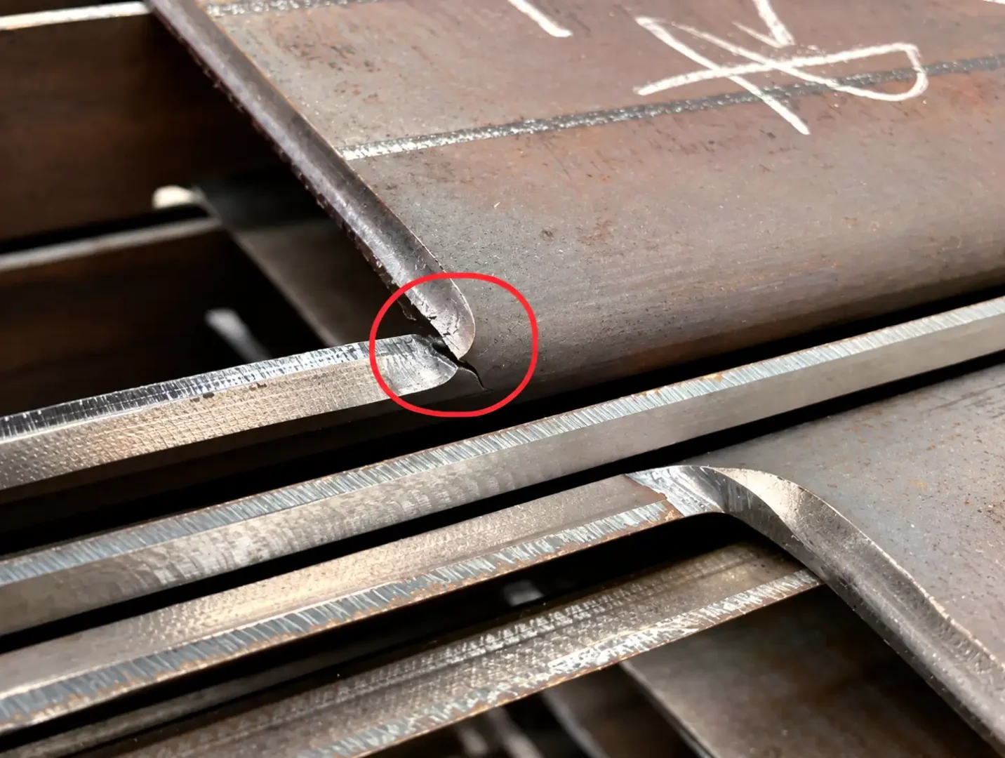
Cracks usually begin at a cut edge and become visible as the part is formed. A laser-cut, sheared, or punched edge can carry burrs or small cracks. Bending loads those weak points, and the crack grows from the edge into the bend.
The usual causes are straightforward:
- Burrs left on the cut edge
- A bend line running parallel to the material rolling direction
- An inside bend radius that is too small
- Local stress concentration close to the bend
Start by checking the edge before it reaches the press brake. Deburring matters, especially when the bend is close to a cut edge. Bend direction matters as well. Where the layout allows it, changing the relationship between the bend line and the rolling direction reduces the chance of a crack starting at the edge.
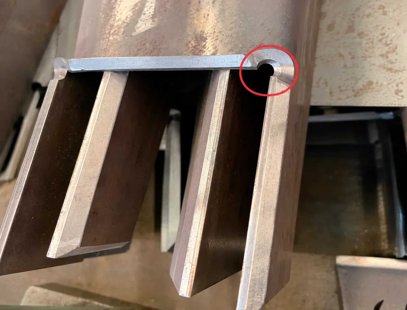
If the geometry concentrates too much stress at a corner, add a relief hole or relief slot near the bend.
A bend relief can stop the crack at the corner
In the U-shaped part shown below, cracking appeared at the corner during forming. A process relief hole was added at the critical location. The hole gives the material room to deform instead of forcing the strain into the edge of the bend.
2. Bending interference
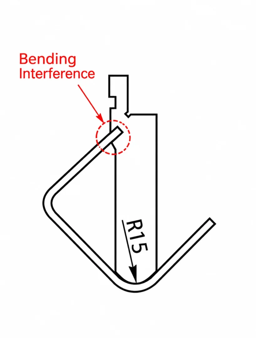
Interference usually shows up on the second or third bend. An already formed flange or wall hits the punch, die, or press brake before the next bend can reach its required position.
The part can look completely reasonable when each bend is considered on its own. The problem only becomes obvious when the partially formed part has to travel through the full bend sequence.
The usual solutions are to change the punch profile, machine the existing punch locally, change the bend sequence, adjust the flange dimensions, or redesign the interfering area.
R15 U-channel: machining clearance into the upper punch
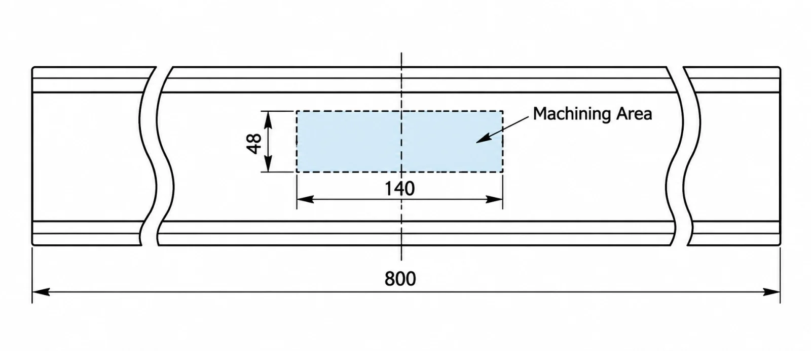
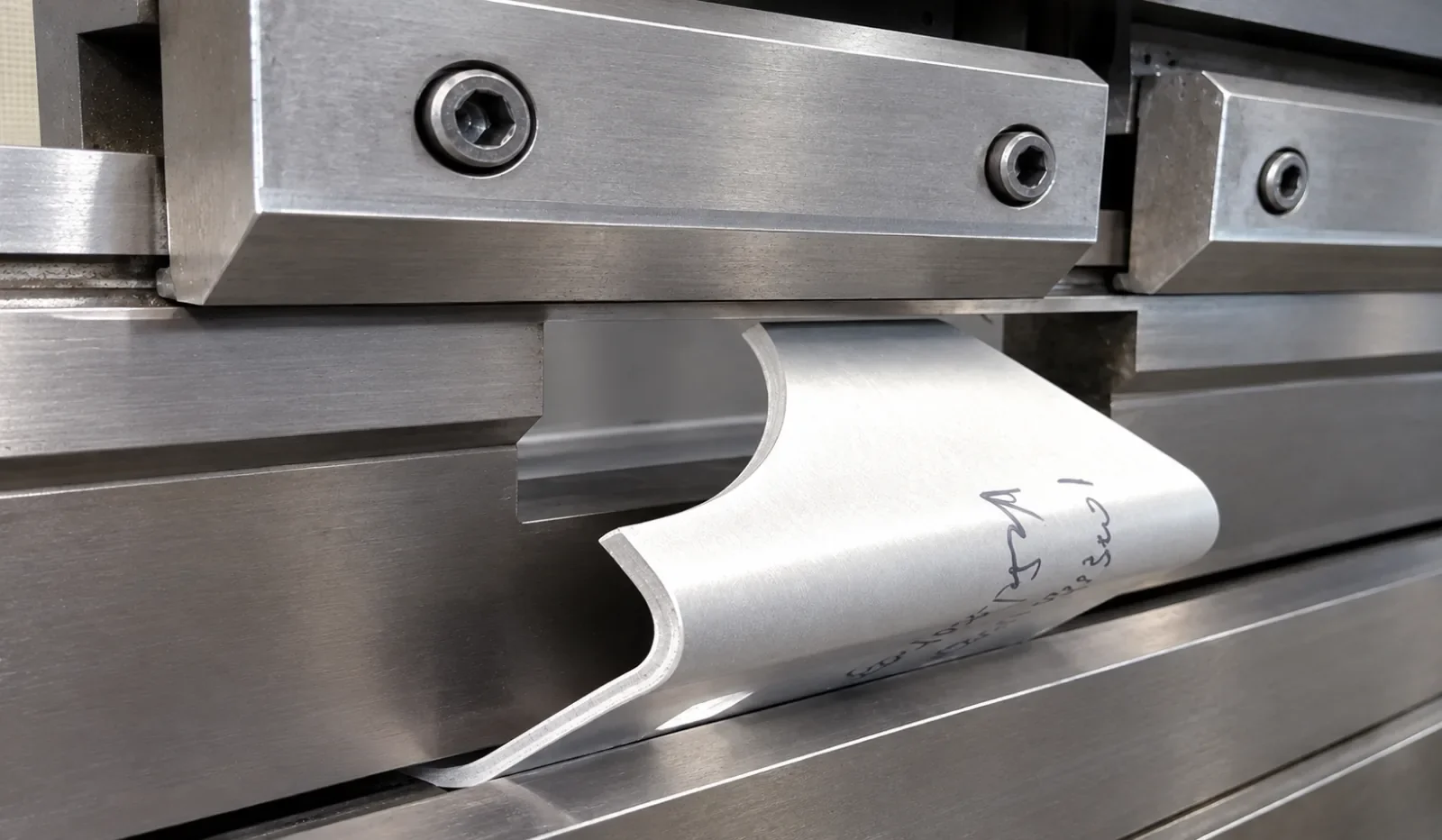
One U-shaped channel had an inside bend radius of R15. During forming, the workpiece interfered with the existing straight upper punch. The solution was not a new 800 mm tool. A 140 × 48 mm clearance section was machined from the middle of the 800 mm long R15 punch.
That clearance allowed the formed section to pass the tool while the rest of the punch remained available for the bend.
3. Bend marks on the surface
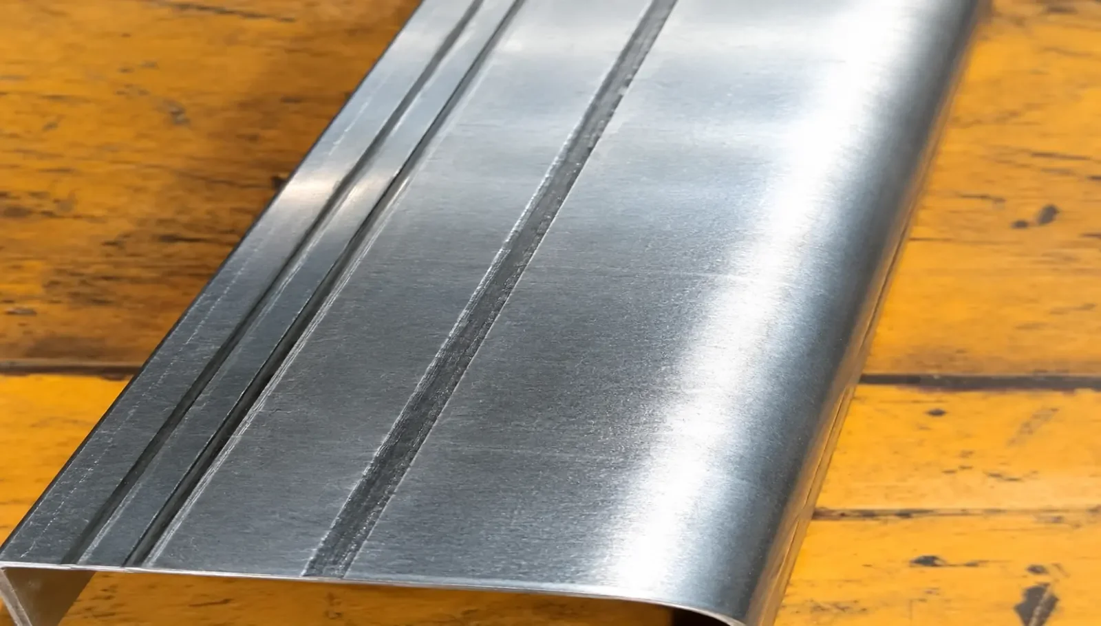
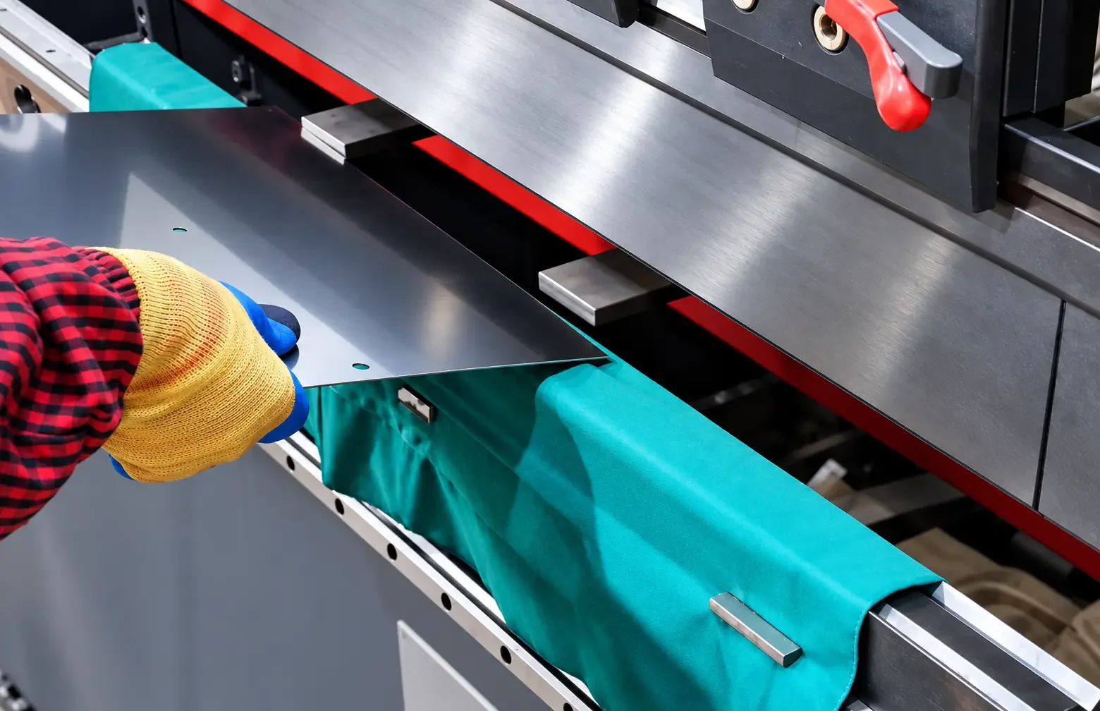
Marks are common on visible sheet metal. During V-die bending, the sheet moves against the die shoulders. Contact pressure and friction can leave a line or an impression on the surface.
That may be acceptable on an internal bracket. It is a different matter on a visible stainless steel panel, an enclosure cover, an appliance part, or an architectural component.
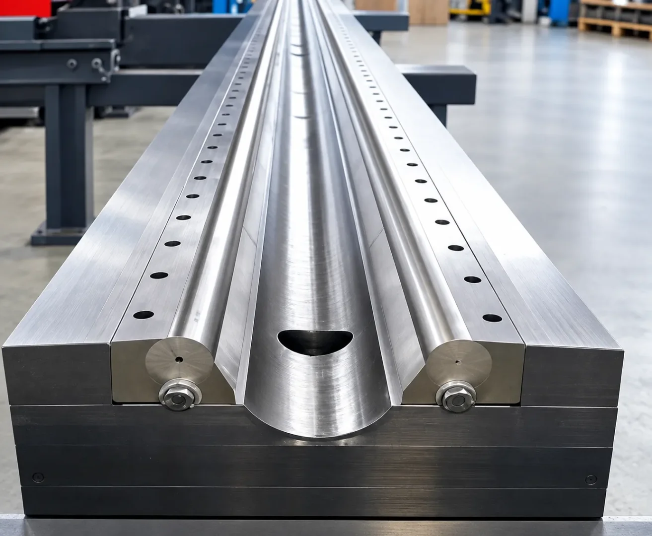
Material hardness, die opening, die shoulder radius, surface condition, and contact pressure all affect the mark. A wider V opening spreads the contact over a larger area. A larger lower-die shoulder radius also reduces the depth of the mark.
Protect the face, or change the contact
A protective pad or film creates a physical layer between the sheet and the tooling. It is a direct way to protect an appearance-critical surface. A roller-type lower die changes the contact itself: the contact surface rolls with the sheet instead of forcing the sheet to slide heavily across fixed die shoulders.
4. Springback after bending
Metal does not always stay where the press brake puts it. During bending, the material deforms plastically and elastically. Once forming force is removed, the elastic portion recovers and the bend opens slightly.
Springback changes with yield strength, elastic modulus, thickness, bend radius, part geometry, and the forming method. The radius-to-thickness relationship also changes how the part responds, so a theoretical bend angle alone is not enough.
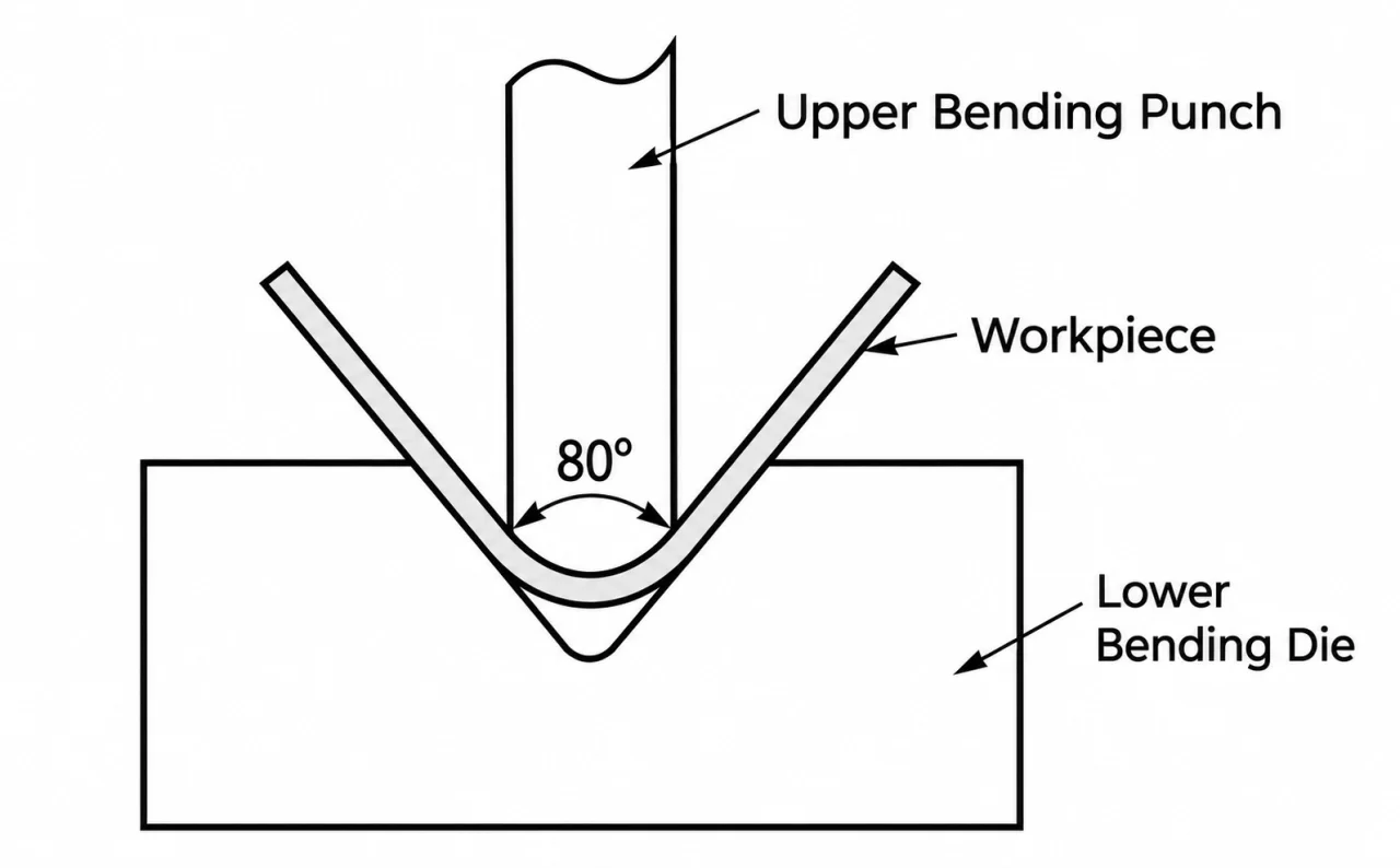
Forming to 80° to finish at 90°
Overbending is the practical answer when the material opens after forming. In the factory example below, an 80° forming condition produced a final 90° bend after springback. Trial bends and recorded process data establish the compensation angle for the job.
5. The part slips during bending
Sometimes the bend is not the problem. The part cannot stay in the correct position long enough to make the bend.
This happens when the workpiece has too little support on the lower die or no reliable edge for the backgauge. The lower die opening may be too wide for the flange. The locating edge may be too short. The part shape may leave no stable backgauge contact, so the workpiece shifts before forming begins.
For this type of air bending, a lower die opening of roughly 4 to 6 times the sheet thickness is a useful process reference. If the flange is too short for the die opening, the sheet will not sit securely on both sides of the V-die.
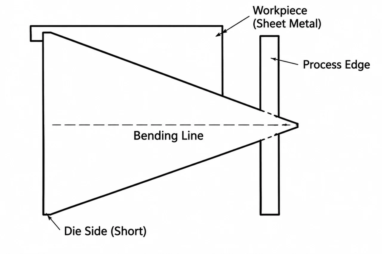
Add a process edge or a locating template
Some complex parts do not have enough straight material for reliable positioning. A temporary process edge can be added to the blank, then removed after bending. For thicker material, a separate locating template can be cut and placed against the backgauge.
6. Forming a large bend radius without a dedicated tool
Large-radius bends create a tooling problem. A project may call for R100, R125, or a larger radius when there is no matching punch and die in the tool set. A dedicated forming tool can be made, but for a small quantity the tool can take longer and cost more than the parts justify.
Multi-step bending provides another route. Instead of forming the full curve in one hit, the arc is built with a sequence of smaller bends.
R125 radius formed with R45 tooling and eight bends
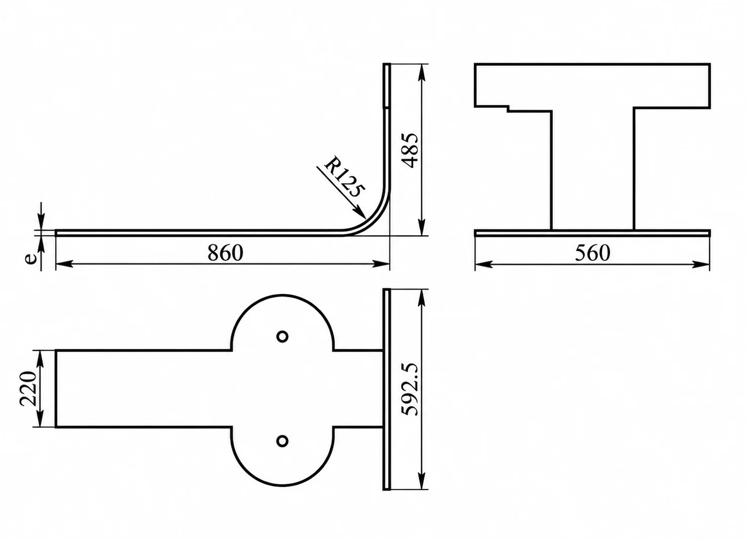
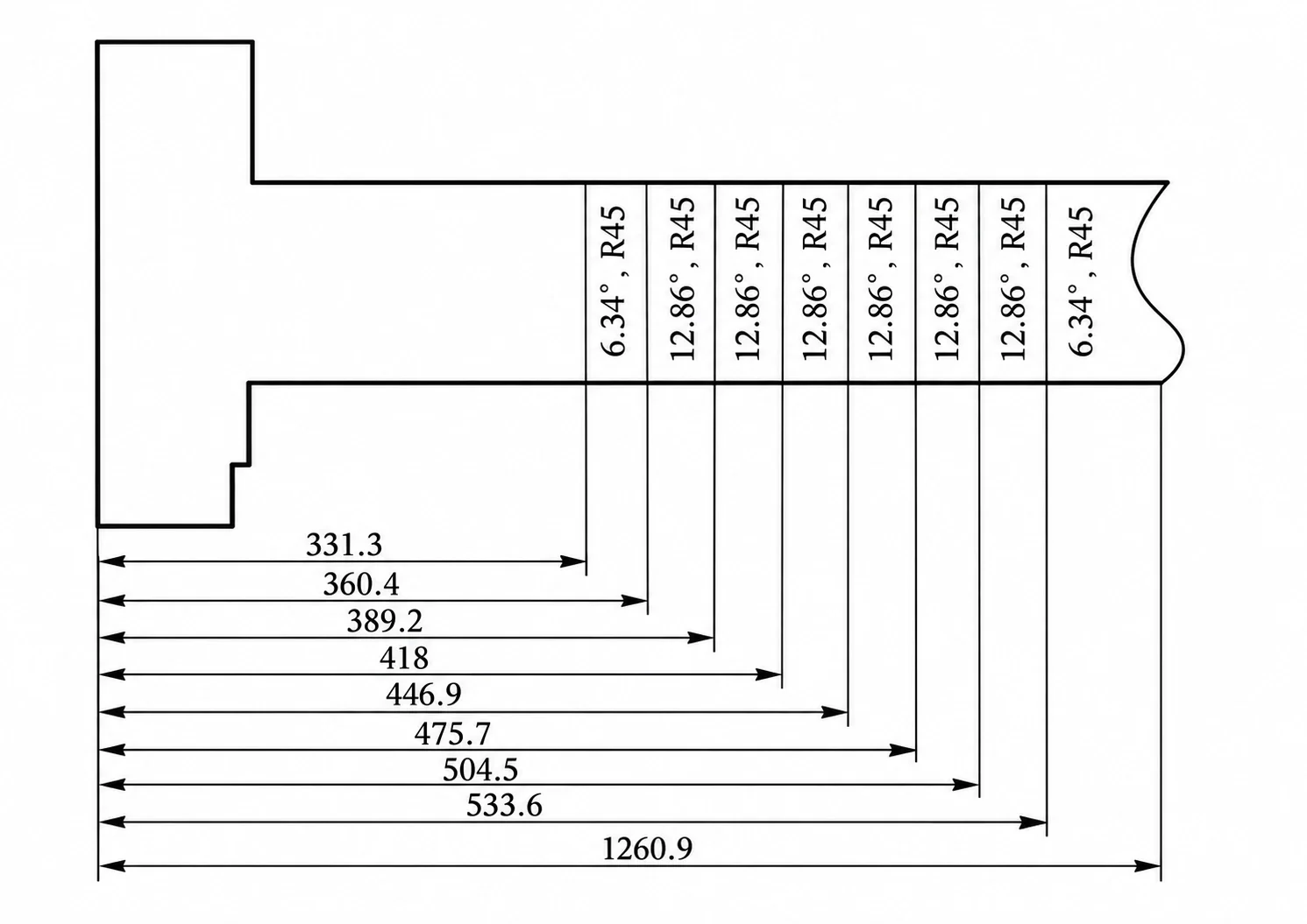
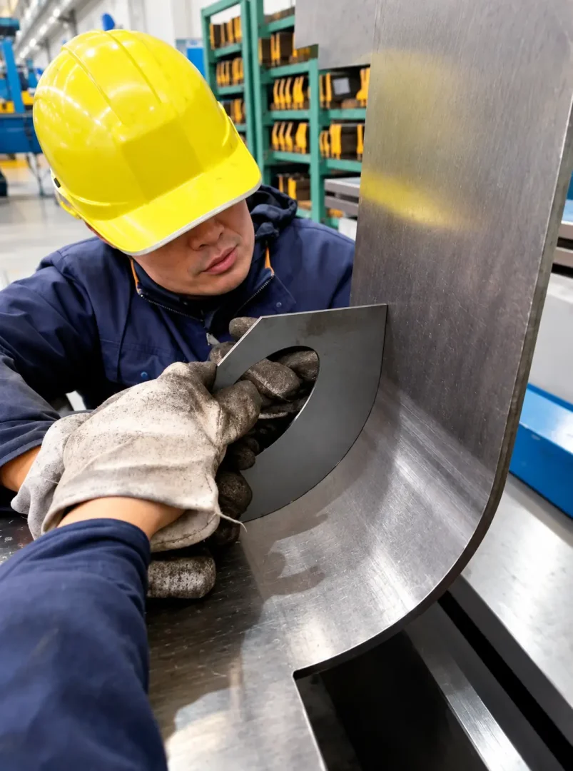
The part below required an R125 mm, 90° bend. The radius was modeled in 3D, then divided into multiple forming steps. An R45 forming radius was used, and the large arc was made with eight individual bends.
The flat pattern defined the bend positions and the angle of each bend before the part reached the press brake. The drawing shows two 6.34° bends at the ends and six 12.86° bends between them.
7. Bulging at the bend edge
The end of a bend can create a different defect. As the material compresses around the bend, metal moves outward at the edge and produces a small bulge. The finished part can become wider at the bend than the original flat profile.
The bulge is more noticeable in thicker material, at a smaller bend radius, and where the bend edge has to remain flush with another component. Grinding can remove it after bending, but the cleaner solution is to plan for the material movement in the flat pattern.
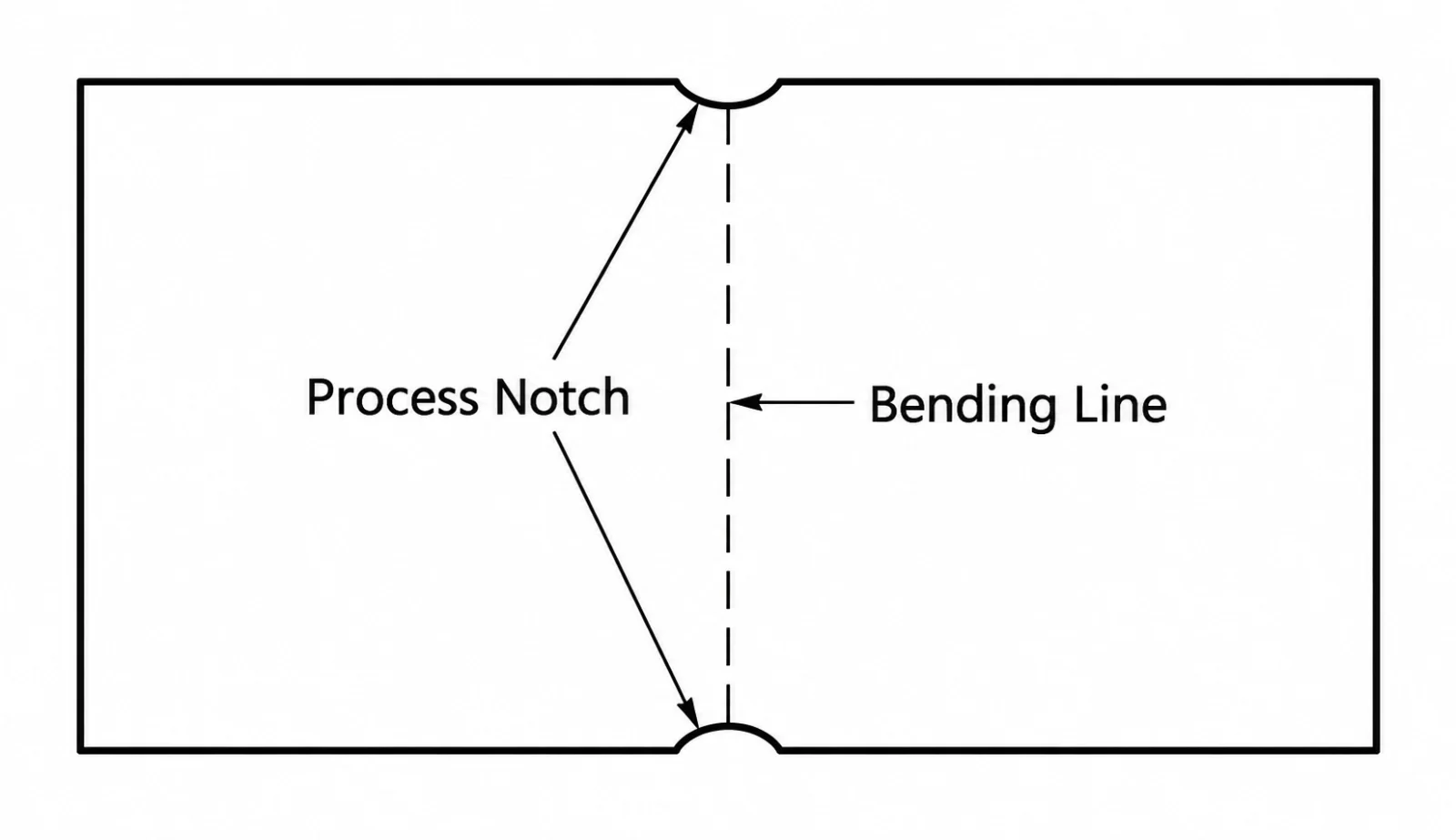
Add a process notch before bending
Place a small relief notch at each end of the bend line. A rounded notch with a diameter greater than about 1.5 times the sheet thickness gives displaced material room to move and reduces the amount that protrudes beyond the required edge.
Check the bend before the part reaches the press brake
Most bending defects are cheaper to prevent than to repair. Review these points before production:
- Bend radius against material thickness
- Bend direction and edge condition
- Tool clearance and bend sequence
- Flange length and backgauge access
- Surface requirement and springback behavior
- Whether a special radius needs special tooling
A thin stainless steel cover with a cosmetic finish and a thick carbon-steel structural bracket may both go through a press brake, but they do not need the same tooling or process. The useful question is always the same: what will this part touch, where will it be supported, and how will the material move while it is being formed?
FAQ
What causes sheet metal to crack at a bend?
Burrs or small defects at a cut edge, an undersized inside radius, a bend parallel to the rolling direction, and local stress concentration can start a crack. Deburring and a relief hole or slot address the problem at its source.
How can a formed flange avoid hitting the punch?
Check the whole bend sequence, not each bend in isolation. A different punch profile, a locally machined clearance section, a changed bend sequence, or an adjusted flange can remove the collision.
Why does a 90° bend open after bending?
The material recovers elastically after the forming force is removed. Overbending compensates for that springback. The illustrated example used an 80° forming condition to obtain a final 90° bend.
Can a large radius be made without a dedicated radius tool?
Yes. A large arc can be approximated with multiple smaller bends. The R125 example in this article used R45 tooling and eight individually located bends.