
A liquid cold plate can look excellent in a thermal simulation and still fail as a manufactured assembly. Failures often begin with an incomplete link between the heat map, coolant, pressure budget, material, sealing method, production process, and qualification plan.
Compared with air cooling, a well-matched liquid loop can remove high local heat with less airflow at the device and a compact heat-transfer interface. System noise, size, and energy use still depend on pumps, heat exchangers, fans, maintenance space, coolant control, and leak protection. Lower device temperature supports reliability only when the complete system remains stable through its service life.
Start the design outside the plate. Define what the heat source needs, what the cooling loop can supply, and what the finished assembly must survive. Draw the channel layout after those limits are clear.
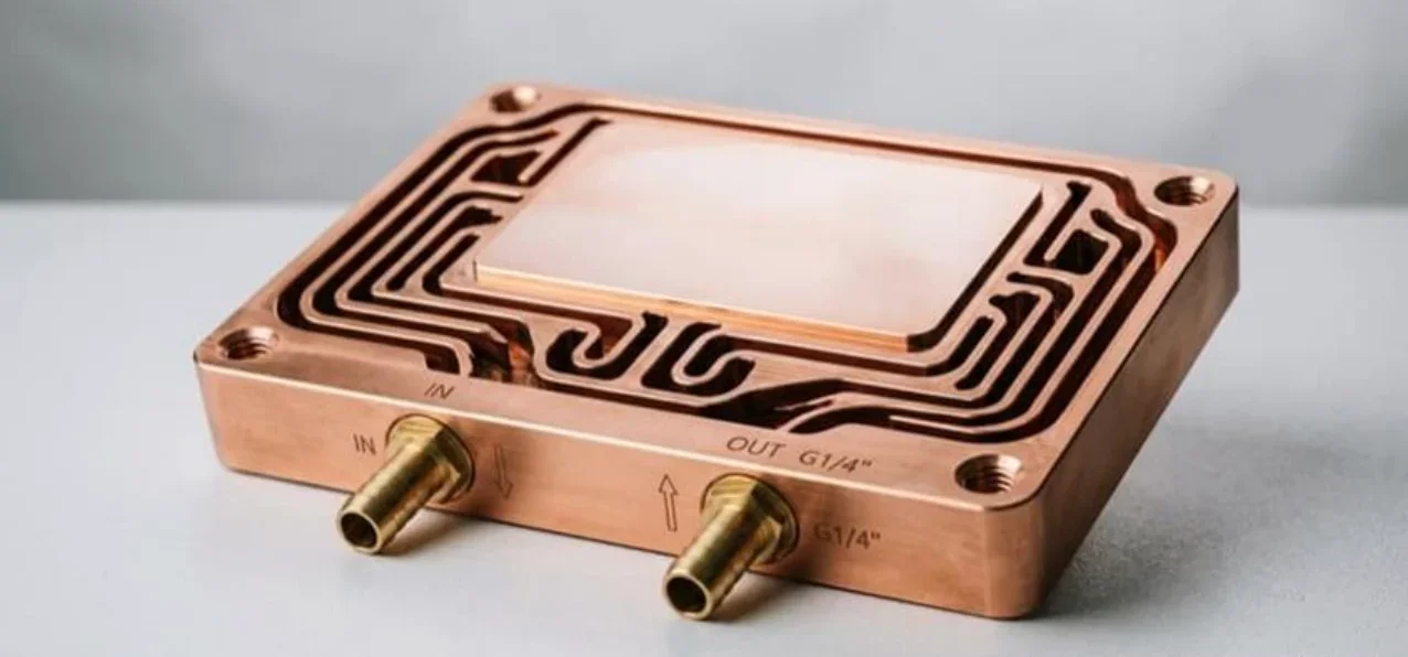
Define Boundary Conditions Before Drawing the Channels
Start with a heat map that records the location and footprint of each heat source, steady and transient power, allowable case or surface temperature, and any temperature-uniformity limit. Total power is only one input. Two devices with the same total heat can need very different plates if one spreads heat over a large area and the other concentrates it under a small package.
The fluid-side inputs need the same level of definition. Specify the coolant and concentration, inlet-temperature range, required flow range, available pressure drop, design pressure, cleanliness level, filtration, storage temperature, and expected service life. Coolant viscosity and corrosion behavior change with temperature and concentration, so a room-temperature water test cannot stand in for every operating condition.
| Input group | Project data to define | Why it changes the plate |
|---|---|---|
| Thermal | Heat map, transient load, maximum case or surface temperature, uniformity | Sets the thermal-resistance budget and where flow is needed |
| Fluid | Coolant, concentration, inlet-temperature range, viscosity, water quality | Changes heat capacity, corrosion risk, sealing, and pressure drop |
| Hydraulic | Flow range, available pressure drop, pump or CDU curve | Limits channel size, length, branch count, and manifold geometry |
| Mechanical | Envelope, mounting pattern, connector loads, flatness, vibration | Controls base thickness, stiffness, retention, and port support |
| Reliability | Service life, pressure and thermal cycles, leak criteria, environment | Defines the qualification tests and acceptance limits |
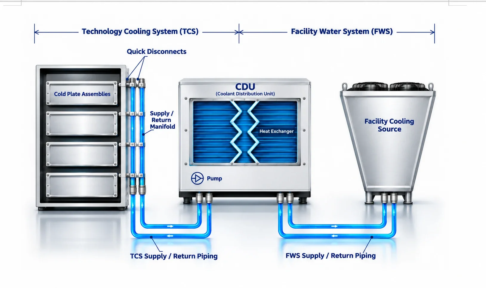
For data-center hardware, the plate is one part of a larger loop. The Open Compute Project Cold Plate Sub-Project defines the technology cooling system, or TCS, as the equipment-side circuit containing cold plates, hoses, manifolds, quick disconnects, and the coolant distribution unit. The CDU commonly transfers heat to the facility water system, or FWS, through a heat exchanger. A pressure-drop target that ignores the manifold, hose, connector, and CDU budget is not a system requirement.
Build the Thermal Path From the Device to the Coolant
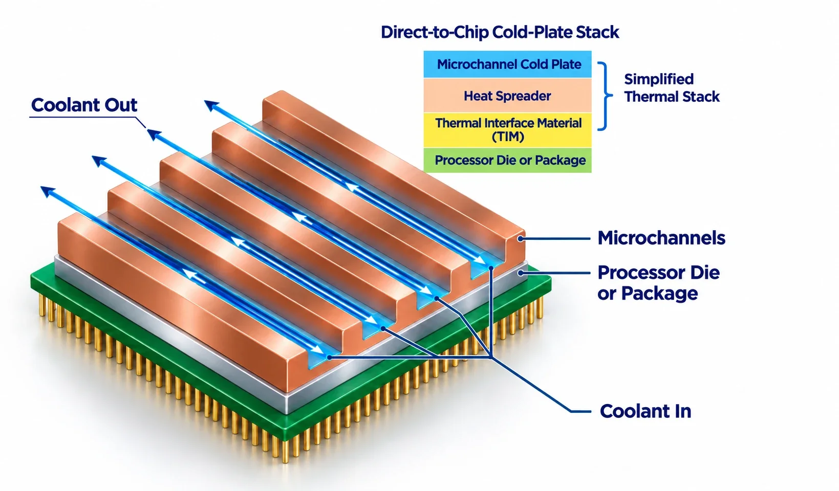
Heat crosses several interfaces before it reaches moving fluid. A useful thermal budget includes the processor package, heat spreader, thermal interface material, cold-plate contact surface, plate base, channel wall, and coolant film. Leaving out one interface can make a material or channel improvement appear more valuable than it is.
Conduction through the solid follows Fourier's law:
q = -kA(dT/dx)
For a cold plate, this relationship explains why conductivity, contact area, base thickness, and distance from the heat source to the channel all matter. A very thin base can reduce conduction distance, but it may not spread a concentrated heat load or resist pressure-induced bowing. A thick base can improve stiffness and lateral spreading while adding mass and conduction distance. The correct thickness comes from the complete heat map and structural load.
For measured performance, a practical cold-plate resistance is:
Rcp = (Tc - Tin) / Q
where Tc is the agreed case or cold-plate surface temperature, Tin is coolant inlet temperature, and Q is the heat removed. The result is meaningful only when the sensor locations, power, coolant, flow, mounting load, and test method are recorded. The OCP cold-plate development and qualification guide recommends measuring thermal resistance and pressure drop at multiple flow points rather than.
Copper vs. aluminum: choose from heat flux, weight and manufacturing route
Copper offers higher thermal conductivity and can reduce spreading resistance under concentrated heat. It is also dense, relatively expensive, and can complicate mass, machining, and joining targets. Aluminum alloys reduce weight and are well suited to machining, extrusion, and some formed or brazed structures, but their lower conductivity may require a different base thickness or channel arrangement.
As a practical starting point, choose copper when a concentrated heat source makes spreading resistance the main limit and the added mass is acceptable. Choose aluminum when lower mass, the manufacturing route, or system cost is the stronger constraint, provided the revised base and channel design still meets the temperature, stiffness, and pressure-drop limits.
| Design factor | Copper cold plate | Aluminum-alloy cold plate |
|---|---|---|
| Thermal spreading | Strong advantage for concentrated heat | Often adequate when the heat area and channel layout are well matched |
| Mass | High | Lower |
| Manufacturing | Machining and joining route must be selected carefully | Broad machining and forming options; alloy and temper still matter |
| Coolant compatibility | Must be checked with every other wetted metal | Oxide behavior and galvanic couples require system-level review |
| Structural data | Use the actual copper grade and condition | Use the actual alloy, temper, product form, and service temperature |
Material strength must come from the specified grade and condition. It cannot be assigned as a generic cold-plate value. For scale, published 6061-T6 data sit in the hundreds, not thousands, of megapascals: Alcoa lists a minimum yield strength of 240 MPa for a stated product condition, while a NIST-hosted aluminum property compilation lists roughly 276 MPa as a typical room-temperature value for 6061-T6/T651. These are reference examples, not allowable stresses for a finished plate.
Flatness, roughness, TIM, and mounting pressure also work as a group. A low roughness value does not correct a bowed surface, and high clamp load does not guarantee a thin, uniform TIM layer if the mounting pattern is poor. Set the interface limits from the processor or battery-module requirement, then inspect the finished and joined assembly in the same state used for thermal testing.
Design the Flow Path Around the Heat Map
Coolant flow removes heat according to the energy balance:
Q = ṁcp(Tout - Tin)
This equation defines total heat removal. The heat map determines where the coolant should flow. High-load regions may need closer channels, more local flow, or a shorter path from the inlet. Lower-load regions may tolerate wider spacing. The design target is controlled temperature and uniformity within the available pump budget.
Channel width, depth, length, wall thickness, turn radius, inlet and outlet position, manifold volume, and branch balance all affect the result. Smaller channels can raise heat-transfer coefficients, but they also increase pressure drop, contamination sensitivity, inspection difficulty, and manufacturing cost. A microchannel plate makes sense only when its thermal benefit justifies those penalties an
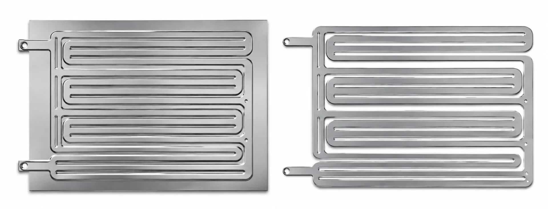
Parallel channels can reduce total path length, but the manifold has to distribute flow evenly. A branch with lower resistance may take more coolant while a remote branch is starved. Serpentine paths avoid some distribution problems but accumulate pressure drop and coolant temperature rise along the route. Neither layout is inherently better.
Select the flow regime from the operating range. Laminar flow can be predictable and efficient at low pumping power. Turbulent or disturbed flow can improve local heat transfer while increasing pressure loss. Use Reynolds number, hydraulic diameter, heat flux, fluid properties, surface condition, and pump power to define that range, then compare the simulation with a measured pressure-drop versus flow curve.
Internal surface quality matters because burrs, excessive roughness, braze residue, weld intrusion, and trapped particles add resistance or create contamination sites. Precision machining can improve the passage. If a coating is proposed, qualify its thickness, adhesion, thermal resistance, coolant compatibility, and particle shedding before adding it to the wetted-surface specification.
Check Strength, Sealing and Manufacturability Before Releasing the CAD
Pressure acts across the full internal projected area, well beyond the channel walls. The resulting load can bow the contact surface, open a cover joint, shift a connector, or change TIM contact. Check the base, cover, ribs, port bosses, fasteners, joints, and mounting feet with the actual design pressure, temperature, connector loads, and support conditions.
Flatness, operating deflection, and local stress are different criteria. Flatness describes the manufactured interface. Deflection describes how that surface moves under pressure, mounting, and temperature. Local stress identifies risk at a port, corner, rib, weld, or bolt feature. A limit such as a single deflection per meter or one stress-concentration factor cannot be used safely without geometry, material, load, nominal-stress definition, and fatigue criteria.
Ribs or cellular supports can increase stiffness, but they may block flow, trap residue, or complicate joining. Finite-element analysis is useful when the geometry, port load, thermal expansion, or joint behavior is difficult to judge by hand. The model should use the specified material condition and realistic restraints. A neat stress plot with a fully fixed edge is not evidence that the installed part will behave the same way.
The manufacturing route should be selected with the channel and qualification plan. Common routes include a machined base with a joined cover, formed plates, tube-in-plate assemblies, and bonded or brazed structures. Each route changes minimum wall thickness, internal access, flatness, heat-affected material, cleaning, leak paths, and inspection. If joining can distort the contact surface, final machining and inspection must occur after the joining operation that causes the movement.
Sealing faces and fluid ports need their own datums and acceptance criteria. Port orientation, thread engagement, quick-disconnect loads, O-ring groove geometry, sealing-surface texture, and service access should be resolved before the channels consume the available material around them.
Qualify the Production Assembly Against the Operating Envelope
Qualification should test the production-equivalent assembly, including the final joint, surface treatment, cleaning process, ports, seals, and contact surface. A prototype that is machined, cleaned, or sealed differently from the production part leaves important risks untested.
| Verification | Record with the result | What the test should reveal |
|---|---|---|
| Thermal resistance | Heat load, flow, Tin, sensor positions, TIM, clamp load | Whether the assembly meets the temperature target across its operating range |
| Pressure drop | Coolant, temperature, flow points, instrument uncertainty | Whether the plate fits the pump or CDU pressure budget |
| Dimensional inspection | Datum scheme, flatness, thickness, port position, inspection state | Whether joining and pressure loading have affected fit or TIM contact |
| Leak and proof pressure | Design pressure, test pressure, medium, duration, leak limit | Whether the assembly remains sealed under the specified proof condition |
| Burst test, if required | Applicable standard, burst criterion, safety controls | Ultimate pressure margin; it is not the same test as proof or leak testing |
| Pressure, thermal, or power cycling | Upper and lower conditions, ramp, dwell, frequency, cycle count | Whether the expected service history damages joints, seals, or contact flatness |
| Corrosion and coolant compatibility | Full wetted-material list, coolant chemistry, temperature, exposure time | Whether material couples, coatings, seals, and residues remain stable |
| Shock and vibration | Fixture, axes, spectrum, duration, post-test leak method | Whether ports, joints, and mounted hardware survive the product environment |
| Cleanliness and internal inspection | Particle limit, flushing method, X-ray or sectioning plan if needed | Whether passages are open and free of damaging residue or debris |
Proof, leak, and burst tests must not be merged into one statement. The correct pressure basis depends on the product and the applicable safety or piping standard. The OCP Cold Plate Cooling Loop Requirements, Revision 2 notes that interconnecting piping and information-technology equipment can fall under different pressure rules. A value such as 1.5 times working pressure is therefore not a universal cold-plate burst requirement.
Cycle count also comes from the expected service history. A useful plan defines the pressure or temperature amplitude, ramp and dwell, frequency, coolant, operating temperature, total cycles, and post-test acceptance criteria. A large number by itself, including 100,000 cycles, does not show that the intended failure mechanism has been tested.
How Application Constraints Change the Cold-Plate Design
The same workflow applies across industries, but the dominant constraints change.
| Application | Main thermal target | Constraints that often dominate |
|---|---|---|
| EV battery | Cell or module temperature uniformity | Pack envelope, vibration, pressure and thermal cycling, corrosion, service life |
| AI and data center | Heat capture at high component density | TCS flow and pressure, serviceability, leak detection, warm-water conditions |
| 5G outdoor equipment | Stable electronics temperature in changing ambient conditions | Compact packaging, corrosion, sealing, maintenance access |
| Aerospace electronics | High heat removal within a low-mass envelope | Mass, vibration, pressure, temperature extremes, traceable qualification |
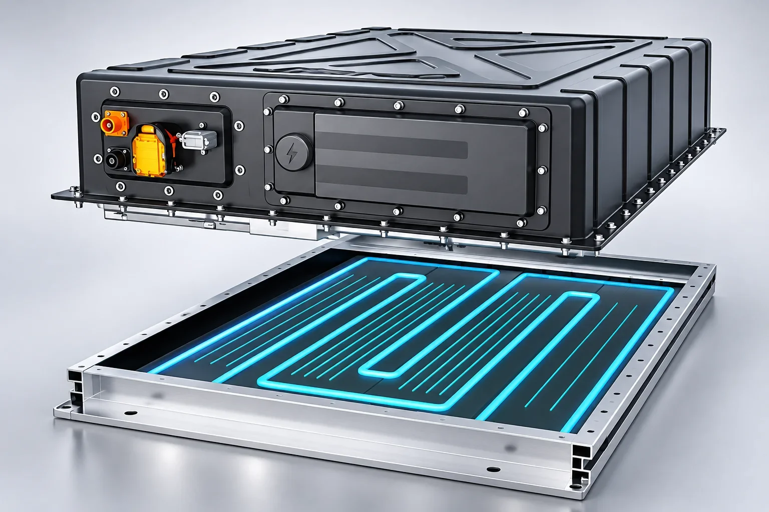
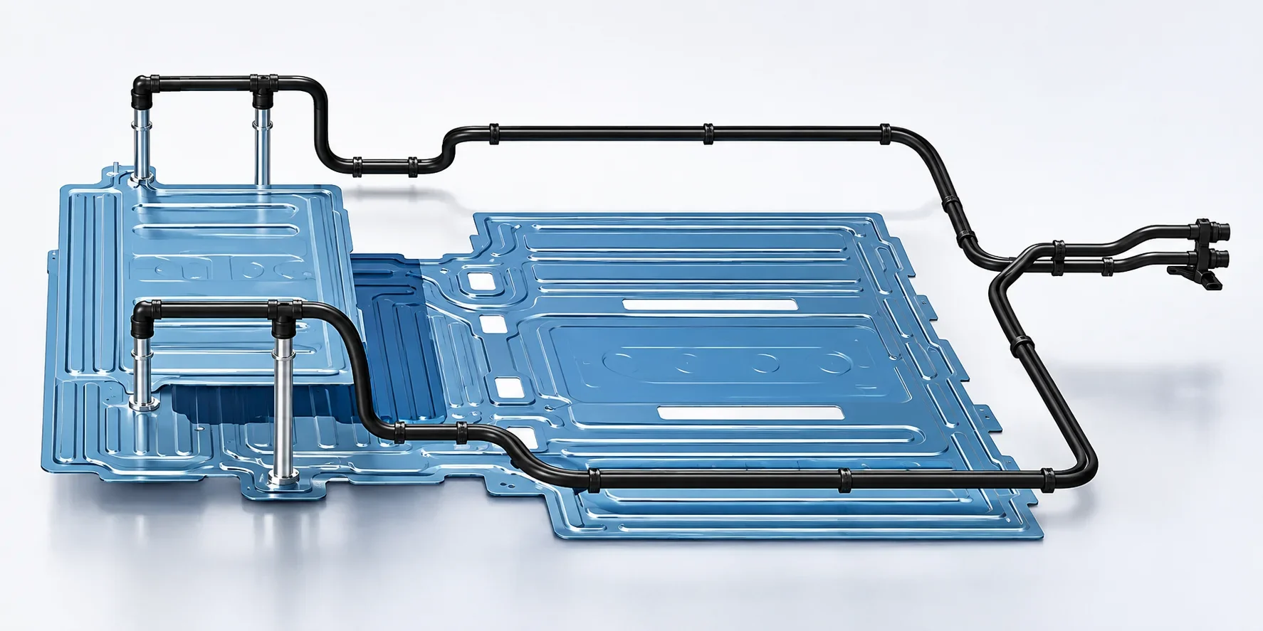
Current AI systems show how platform-specific the boundary conditions can be. NVIDIA documents cold plates on CPUs, GPUs, networking, and storage components in its DGX Vera Rubin NVL72 hardware guide. A separate Vera Rubin platform description cites a 45°C coolant inlet for that warm-water design. This is a useful system example, not a default inlet temperature for other racks or applications.
A Practical Review Checklist for RFQ, DFM and Prototype Approval
Before requesting a quotation, provide the 3D model and envelope, heat map, maximum device temperature, coolant specification, inlet-temperature and flow ranges, available pressure drop, design pressure, life-cycle profile, mounting loads, flatness requirement, ports, and expected annual volume. Missing inputs should be listed as assumptions rather than hidden in the price.
Before releasing a prototype, confirm the material grade and temper, TIM and mounting condition, base thickness, channel and manifold geometry, cover joint, sealing lands, port datums, surface treatment, internal cleaning, inspection access, and production-representative manufacturing route.
Before production approval, match the final design to its reports. Thermal resistance and pressure drop should be shown across the specified range. Leak and proof tests should name their pressure basis. Dimensional, cleanliness, corrosion, cycle, shock, and vibration results should refer to the final joint, coating, seals, and ports.
Approve the design only when the thermal path, hydraulic budget, structure, manufacturing route, and test evidence all describe the same finished part. Material choice and microchannel geometry are two inputs to that decision.
Frequently Asked Questions
What information is needed before designing a liquid cold plate?
At minimum: the heat map, allowable device temperature, coolant and inlet-temperature range, flow range, available pressure drop, design pressure, envelope, mounting condition, flatness requirement, service-life cycles, and leak criteria. Port and service constraints should be included before the channel layout is fixed.
How should pressure drop be balanced against thermal resistance?
Measure or simulate both across the same flow range. Smaller passages and higher velocity may improve heat transfer, but the plate must stay within the pump or CDU pressure budget after hoses, connectors, and manifolds are included.
When does a microchannel cold plate make sense?
Use microchannels when the heat flux and footprint need high local heat transfer, the pump can support the added pressure drop, the manufacturing process can hold the required features, and the loop can control particles and corrosion. For a large, moderate-flux heat source, wider channels may meet the temperature target with lower pressure drop and easier contamination control.
Is copper always better than aluminum for a cold plate?
No. Copper has higher conductivity, while aluminum usually offers lower mass and a wider range of economical forming and machining options. The decision also depends on stiffness, joining, coolant compatibility, galvanic couples, cost, and production volume.
What tests should a liquid cold plate pass before production?
The plan normally includes thermal resistance, pressure drop, dimensional inspection, leak and proof pressure, coolant compatibility or corrosion, cleanliness, and the shock, vibration, pressure, thermal, or power cycles relevant to the product. The test conditions and pass criteria must come from the actual application.
Is 1.5 times working pressure a universal cold-plate test requirement?
No. Proof, leak, and burst tests serve different purposes, and their pressures depend on the applicable product, piping, and safety requirements. State the governing standard, design pressure, test medium, duration, and acceptance criterion instead of copying one multiplier into every specification.