
A rack can look complete in CAD and still create trouble when technicians start working on it. A manifold can block a power whip. A rear door can become too heavy to handle safely. Hoses can leave no room to disconnect a server. Those problems are often built in before the sheet metal is designed, when the project starts with an “air-cooled” or “liquid-cooled” label instead of the actual heat path.
Start by defining how the IT equipment rejects heat. Then check what the facility can support. Only then should the rack be laid out around the interfaces that must fit, move, and remain serviceable. Cabinet size, structure, materials, doors, rails, and inspection criteria follow from those decisions.
Cooling matters, but the cooling label alone does not define the rack.
Choose the rack in this order
- Define the heat-transfer boundary. Is heat leaving the server through room air, cold plates, a rear-door heat exchanger, or a dielectric-fluid tank?
- Check the facility boundary. Can the room air system, liquid loop, controls, redundancy plan, and maintenance process support that architecture?
- Design the installed rack, not an empty cabinet. Model the rails, power, cables, manifold, quick disconnects, hose sweep, door movement, load path, and technician access together.
If cabinet selection starts before the heat path and facility boundary are settled, a nominally “liquid-ready” rack can turn into an expensive packaging problem.
Step 1: identify how the IT equipment rejects heat
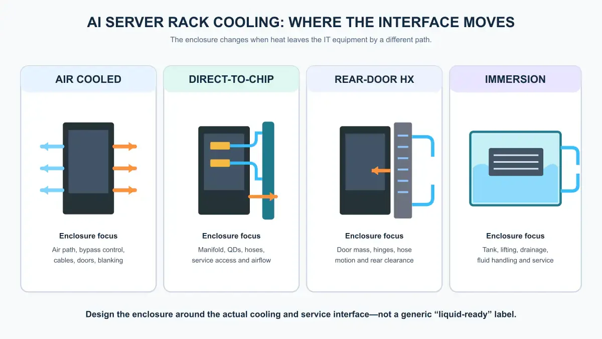
“Liquid cooled” covers several mechanical conditions. Direct-to-chip cooling, rear-door heat exchange, and immersion cooling move heat out of the system at different points. The enclosure requirements change with them.
Air-cooled racks
For an air-cooled server, the rack has to preserve the intended room-air path with the final server population, cable bundles, doors, blanking panels, filters, and containment arrangement installed. A door’s open area is only one input. Two doors with the same nominal open area can create different resistance because of the hole pattern, stiffeners, filters, hinges, or an inner skin.
The final cabinet assembly has to support the required airflow and inlet conditions at the deployed server load. Looking open enough is not a useful test.
Direct-to-chip cold-plate racks
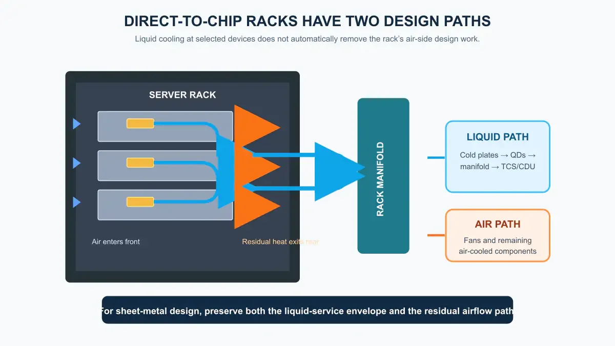
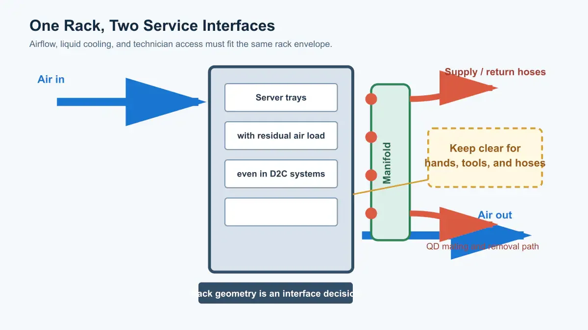
In D2C cooling, cold plates remove heat from named components such as CPUs or GPUs. A supply-and-return manifold distributes liquid to the servers. Power supplies, memory, storage, networking, and other components may still rely on airflow.
The rack therefore has two paths to accommodate: a liquid path for the cooled devices and an air path for the remaining load. The server supplier should define the liquid heat-capture fraction and residual air load. The enclosure has to make both paths workable.
Rear-door heat-exchanger racks
A rear-door heat exchanger transfers heat from server exhaust air to a liquid loop at the back of the cabinet. It may be passive or fan assisted. Mechanically, it is a door system that carries cooling hardware.
Its interface drawing needs to account for filled mass, hinge moment, latch function, hose movement, door swing, rear-aisle clearance, condensate control where relevant, and the removal procedure.
Immersion systems
Immersion cooling places IT hardware in dielectric fluid. Its enclosure is not a conventional 19-inch cabinet with extra plumbing. The design must account for fluid compatibility, lid access, lifting, sealing, drainage, spill management, service fixtures, fire strategy, and floor loading.
Step 2: confirm what the facility can support
The same server can require different rack choices in an existing data hall and in a new AI deployment.
For an air-cooled project, confirm the available air path, containment arrangement, inlet conditions, room heat-rejection capacity, and the final cable population. For D2C or rear-door cooling, also define the liquid boundary: where supply and return connect, how liquid is distributed, where heat is rejected, and how the system is monitored and serviced.
- PUE is a data-center metric, not a rack specification. A rack can influence airflow resistance and serviceability, but it does not have a fixed PUE value of its own.
- There is no universal rack-kW cutoff for liquid cooling. The practical boundary depends on the actual server, its heat-capture arrangement, air path, liquid temperatures, containment, redundancy plan, operating conditions, and facility infrastructure.
The project needs a direct answer to two questions: Can the site support the server’s intended heat path? Can the rack connect to that system without becoming difficult to operate or maintain?
Step 3: turn the cooling system into rack interfaces
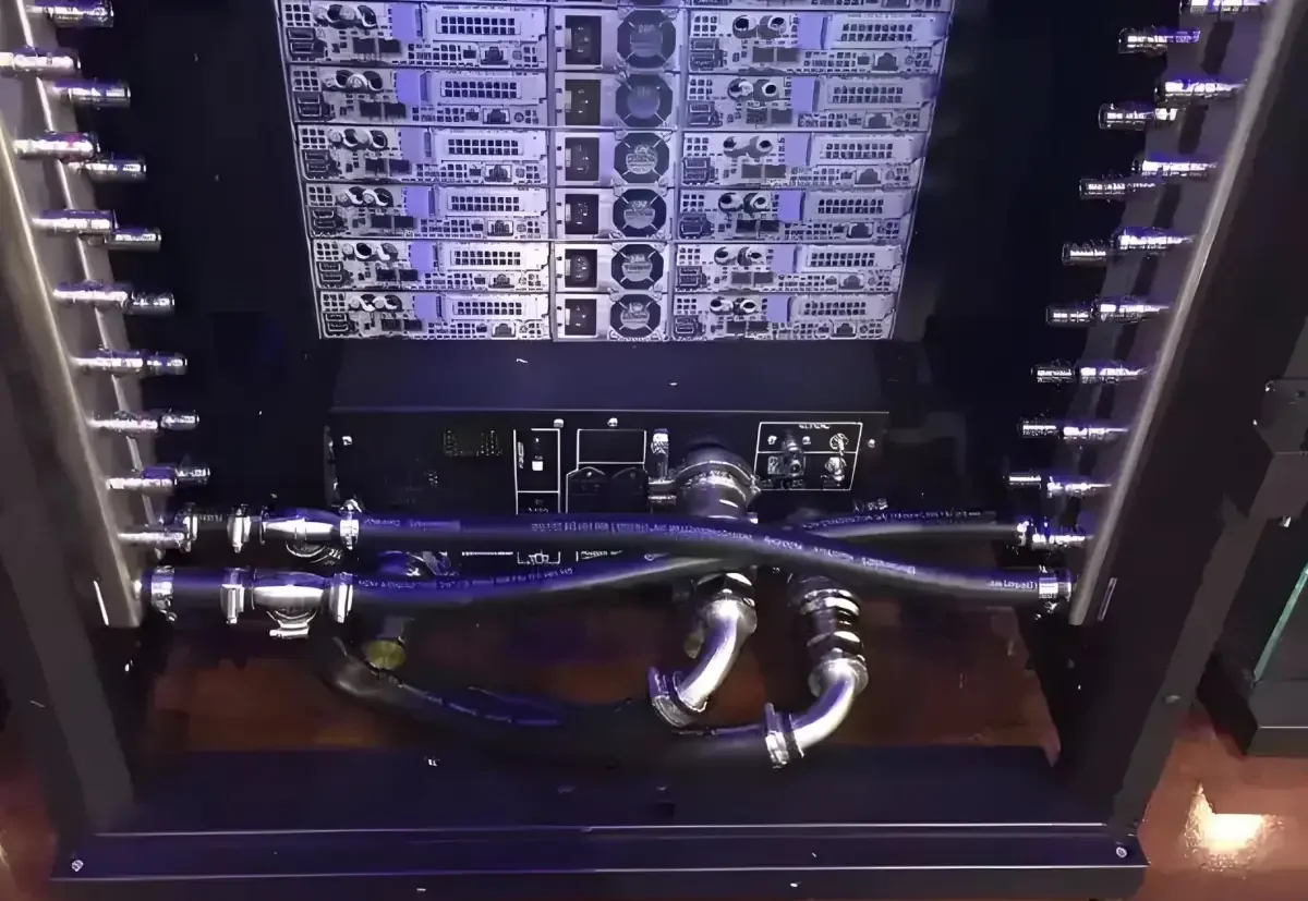
Once the heat path and facility boundary are known, they have to become rack interfaces. On a liquid-cooled rack, the manifold adds filled weight, connection forces, shipping vibration, and repeated service loads. It also occupies the same rear volume needed by power distribution, network cabling, rail latches, and the rear door.
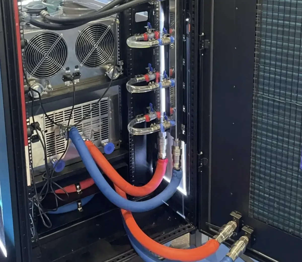
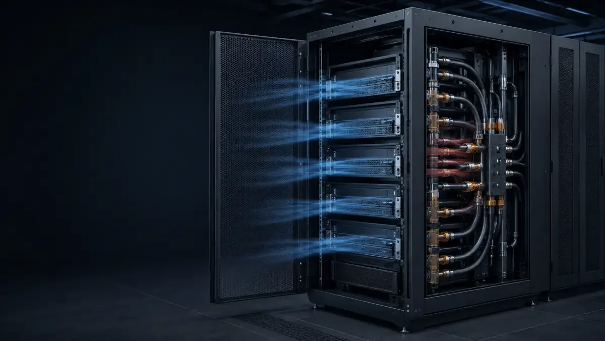
The project photo above shows the interface problem: hoses, valves, distribution hardware, airflow equipment, cables, an open door, and service access all occupy one envelope. Each part can fit on its own drawing. That does not mean the assembly will be serviceable.
Reserve a real service zone for the manifold
The manifold bracket needs a defined mounting datum, local stiffness, and enough adjustment to absorb normal build variation without drifting into the server-removal path. A PDU, vertical cable manager, and manifold cannot all claim the same rear corner.
Before rear rails are released, model the QD mating and unmating path, hose sweep, torque-tool access, isolation-valve reach, server removal direction, and rear-door clearance. OCP publishes a blind-mate manifold specification for Open Rack V3 and related rack specifications; use the actual platform documentation rather than assuming a generic interface.
Review hoses, drips, and mixed materials together
Use the hose supplier’s minimum bend radius and the QD supplier’s mating envelope. Where hoses can contact sheet metal, protect edges and restrain the hose without pinching it. A drip tray or leak-detection cable may make a small release easier to see, but it should not block inspection, hide fittings, or create an area that cannot drain and be cleaned.
The wetted-material review applies to the complete liquid path: manifold, seals, QDs, hoses, valves, coolant, and any metal components exposed to a leak. Where stainless steel, aluminum, zinc-coated sheet, and painted carbon steel meet, check galvanic contact, drainage, coating damage, and the intended bonding path.
Put these inputs on the controlled rack drawing
- Manifold: supply/return orientation, mounting datum, filled mass, isolation, removal direction, and connection forces.
- Quick disconnects: hand-mate or blind-mate type, keying, drip performance, mating envelope, tool access, and replacement method.
- Hoses and cables: bend radius, abrasion protection, restraint, cable volume, hot-swap path, PDU position, and door interference.
- Thermal boundary: server-declared liquid class, CDU approach temperature, site dew point, insulation, sensors, and shutdown response.
- Responsibility boundary: ownership of the frame, manifold, QDs, loop pressure test, flushing, water chemistry, and commissioning.
Step 4: size the rack around installed equipment
A rack’s outer height, width, and depth should come from a dimensional stack-up. Include the chassis, rail kit, connector bodies, cable-management hardware, PDU or busbar, manifold, QDs, hose bend, door structure, and the space a technician needs to install and service them.
Do not mix rack ecosystems
A 19-inch cabinet and an OCP Open Rack are not interchangeable mounting assumptions. One rack unit is 44.45 mm high; OCP rack specifications define their own equipment, power, rail, and liquid-interface arrangements. Name the base-frame specification, rails or adapters, power interface, and manifold interface on the project drawing before selecting the cabinet geometry. ASHRAE Handbook, Chapter 20 OCP Rack and Power specifications
Use common sizes as starting envelopes, not final answers
For 19-inch enterprise cabinets, early discussions often start around 42–48U, 600 or 800 mm (23.6 or 31.5 in.) wide, and 1000 or 1200 mm (39.4 or 47.2 in.) deep. An 800 × 1200 mm cabinet can provide useful room when vertical PDUs and a side or rear manifold must coexist.
Those dimensions are a starting envelope, not a released design. The rail-adjustment range, server depth, connector bodies, cable bend radius, QD access, rear-service volume, and door swing decide whether the envelope is actually usable.
Define the load case, not only the load rating
For early design discussions, a full-height AI rack may be scoped around a static payload in the 1200–2000 kg (2646–4409 lb) range. This is not a catalog promise or a universal requirement. The final structure depends on the released payload map, center of gravity, partial-population cases, liquid-filled hardware, rear-door moment, caster or leveling-foot position, anchorage, floor rating, and shipping condition.
A 1500 kg rack with dense GPU trays high in the cabinet is not mechanically equivalent to a uniformly loaded 1500 kg rack. The critical test should reproduce the actual configuration and record deflection at named points, door and latch operation under load, and residual set after unloading.
Step 5: choose materials and fabrication details around the load path
Material selection should follow the installed load map and environment. For a dry indoor data hall, cold-rolled steel can be a practical starting material for frames, rails, doors, and panels. Galvanized or galvannealed sheet can add corrosion reserve in selected areas. Type 304 stainless steel can be useful for drip trays and wet-adjacent brackets. Aluminum can reduce panel weight, but stiffness, joining, bonding, and mixed-metal contact need their own review.
The following values are early design-review ranges for fabricated racks. They are not standard-mandated thicknesses or BW capability claims. Section shape, material grade, payload, joint spacing, manufacturing route, and test results can change the final selection.
Reinforce the load path before making every panel thicker
When material cost matters, increasing the thickness of every panel often adds weight without fixing the critical structure. A more focused approach is to reinforce uprights, rail brackets, manifold mounts, base corners, and caster or anchor zones, then use formed returns and hems to stiffen removable panels.
The same logic applies to corrosion strategy. In a controlled indoor room, an all-stainless rack may be unnecessary. A powder-coated carbon-steel frame with stainless wet-adjacent parts can be a practical split, provided mixed-material joints receive appropriate attention to isolation, bonding, coating damage, and drainage.
Release bends, joints, and finish together
For many cold-rolled sheet parts, an inside bend radius around 1.0–1.5 times material thickness is a useful starting discussion. It is not a universal rule: alloy, temper, grain direction, tooling, cosmetic face, and formed geometry still govern. Holes, slots, and self-clinching hardware need to respect the limits of the fastener and tooling system. On long uprights, fixture datums and weld sequence can matter more than a tighter flat-pattern tolerance.
For indoor powder coating, a 60–100 μm (2.4–3.9 mil) dry-film thickness may be used as a project range. The drawing should also define pretreatment, color and texture, cure requirements, masked bonding points, threaded features, rail fits, cosmetic zones, measurement method, and acceptance criteria. ASTM D3359 and ASTM D7091 are relevant references for adhesion and nondestructive dry-film-thickness measurement, but the applicable method and acceptance level must be defined by the project.
Step 6: verify the installed rack and liquid hardware separately
A square frame does not prove that a manifold is leak tight. A passed liquid pressure test does not prove that server rails align or that a rear door clears the hoses. The inspection plan needs two boundaries: one for enclosure geometry and function, and another for installed cooling hardware.
The table below retains example starting targets from the original article. They are examples, not universal acceptance requirements. A released drawing and test procedure must state the datum, support condition, measurement method, temperature, payload, and pass/fail rule.
For the liquid hardware, the approved procedure, not a generic rack checklist, must define the test medium, pressure, stabilization time, hold time, allowable decay, temperature compensation, and safety controls. Pressure decay, vacuum decay, tracer gas, and other methods have different application limits. A proof pressure such as 1.25–1.5 times operating pressure is sometimes used in engineering programs, but must not be applied blindly across seals, QDs, sensors, or assembled servers.
The record should also identify wetted materials, cleanliness or flushing status, connection torque where applicable, sensor continuity, valve position, and protective caps for shipping. If a rack fabricator supplies only brackets and a drip tray, the final record should not imply that an uninstalled or separately supplied liquid loop was qualified.
UL lists rack/cabinet systems and immersion cabinets/enclosures as separate data-center product categories. That is another reason to define the actual cooling architecture before making compliance or test claims.
Step 7: apply the sequence to the actual project
Retrofit in an existing data hall
If the existing air path has measured capacity at the intended load, an air-cooled rack may remain the lowest-risk solution. In that case, the first improvements may be containment gaps, door pressure drop, cable congestion, blanking, and commissioning, rather than a change to the cabinet type.
If a limited group of CPU or GPU nodes is the constraint and the site can support a CDU or facility-water connection, D2C cooling may preserve much of the existing rack ecosystem. A rear-door heat exchanger may suit a retrofit where room heat rejection is the main constraint. Neither is a drop-in answer until the rear service zone, hose route, downtime, controls, water quality, residual air load, and commissioning plan are resolved.
New high-density AI pod
For a new pod, select the server cooling boundary and facility heat-rejection path together. Define the D2C capture fraction, residual airflow, coolant, supply-temperature class, flow, pressure drop, CDU arrangement, and redundancy plan. Then select the 19-inch or OCP rack ecosystem and release manifold, power, cable, structural, and service interfaces as one package.
Immersion may make sense for a platform designed around tank service, but rack density alone does not make it the default. D2C and rear-door systems can offer a more familiar service model, while immersion changes hardware handling, fluid management, lifting, fire strategy, and floor layout. Compare the operating model as carefully as the thermal capacity.
The project record that prevents late rack changes
Before fabrication, one controlled project record should show:
- where heat remains in air and where it moves to liquid;
- the server, facility, and rack interface boundaries;
- the payload map, center of gravity, service envelope, and door positions;
- the selected materials, joints, finish, and wet-adjacent details;
- separate mechanical and liquid-hardware acceptance plans.
That record is more useful than a generic claim about the “best” cooling technology. It shows how the selected IT and facility systems will be installed, connected, serviced, and verified as one working assembly.