
On a sheet-metal enclosure, a small change in welding technique can show up later as a higher bead to finish, heat near a door opening, or a seam that is harder to inspect and coat. But push and drag are not universal quality settings. Their starting point depends first on the welding process.
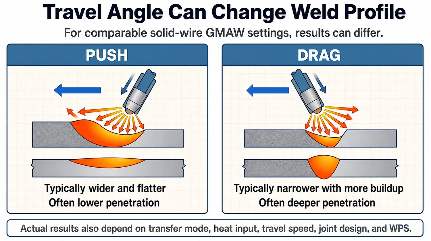
Here is the short answer: slag-forming processes such as SMAW (stick) and many FCAW applications commonly start with a drag angle; solid-wire GMAW (MIG) often starts with a push angle. The reason is not personal habit. It is what has to stay controlled around the leading edge of the weld pool.
For a sheet-metal buyer or design engineer, the useful outcome is not to prescribe a torch angle on every drawing. It is to define the finished weld requirement, then let the approved welding procedure select the technique.
Push and Drag Describe Travel Angle
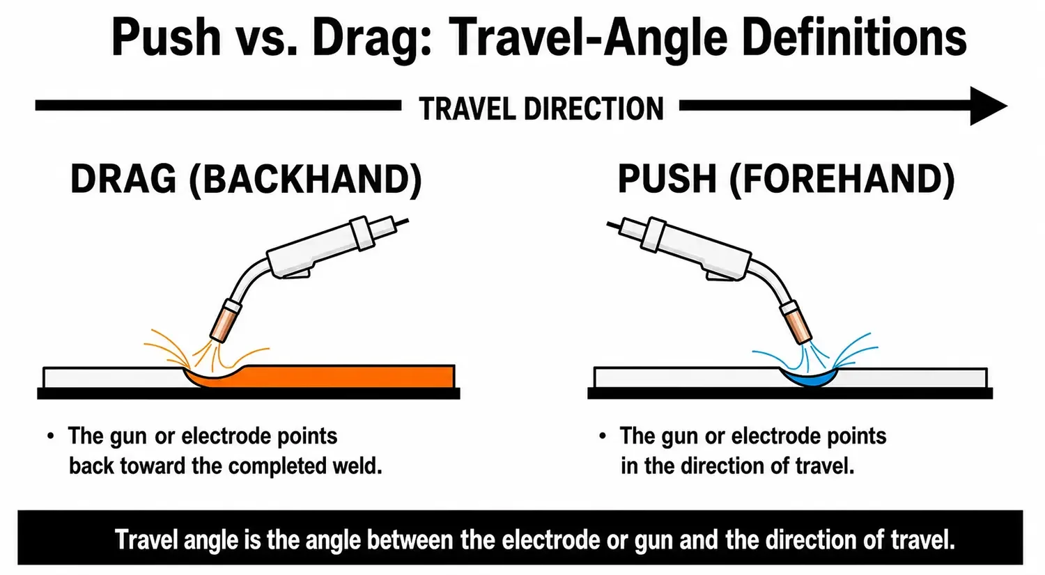
Push and drag describe the angle of the gun or electrode relative to the direction of travel.
- Push welding (forehand) points the gun or electrode toward the direction of travel.
- Drag welding (backhand) points it back toward the completed weld.
This is different from the work angle, which positions the tool relative to the two faces of a joint.
Why the Usual Direction Changes: Slag Versus Shielding Gas
This is the core distinction.
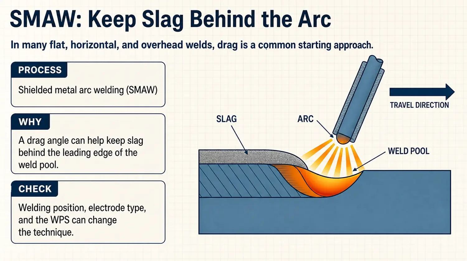
Stick welding (SMAW) and flux-cored welding (FCAW) create a slag system. In many flat, horizontal, and overhead applications, dragging helps keep that slag behind the active leading edge of the puddle. If slag moves ahead of the arc, it can obstruct access to the joint and contribute to defects such as slag inclusion or incomplete fusion.
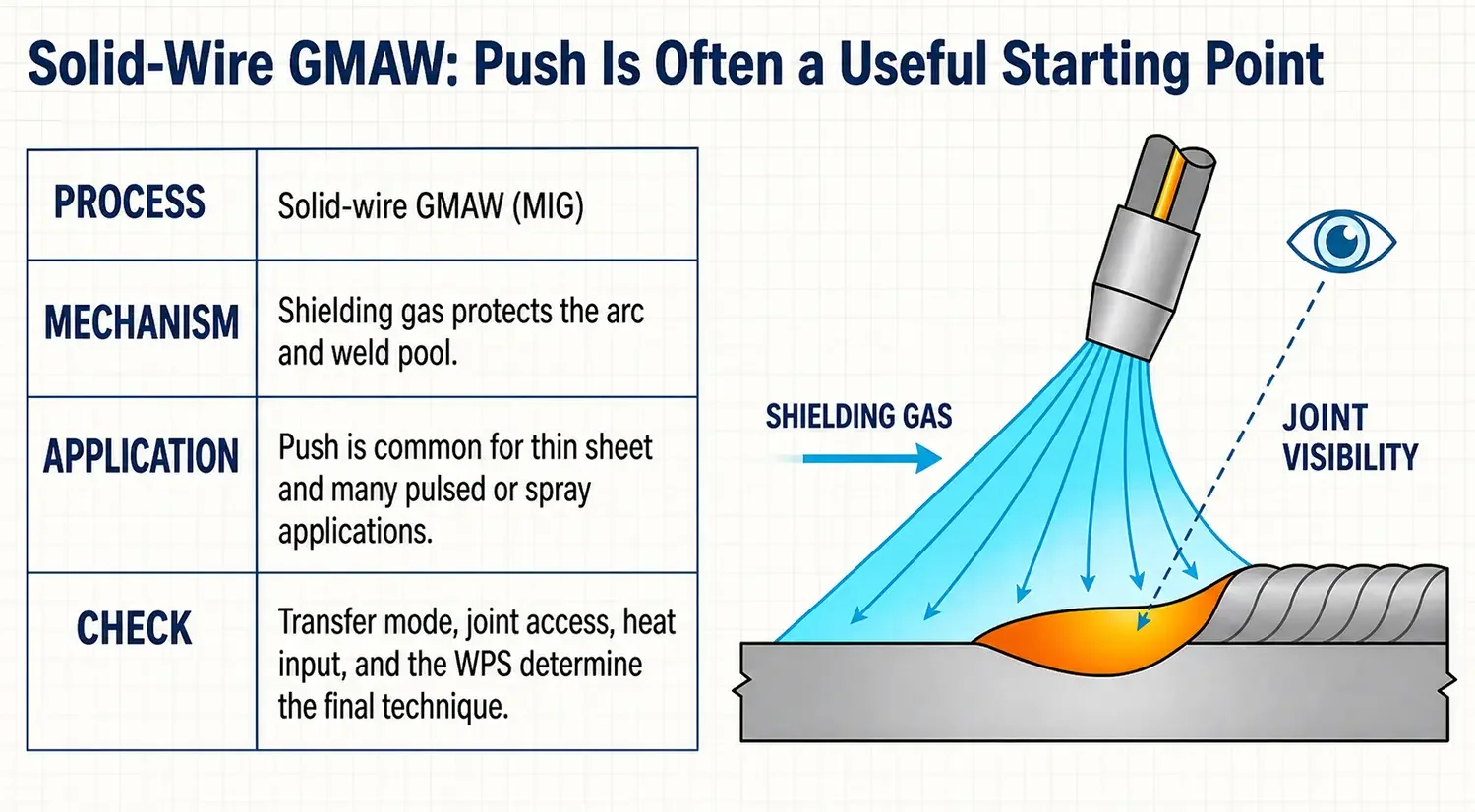
Solid-wire GMAW does not create that slag layer. On thin sheet, a push angle is often a useful starting approach because it can improve sight of the leading edge and, with comparable settings, tends to produce a wider, flatter weld profile than dragging. The GMAW shielding gas must also cover the weld pool effectively; nozzle condition, gas flow, drafts, stickout, travel speed, and joint access all matter.
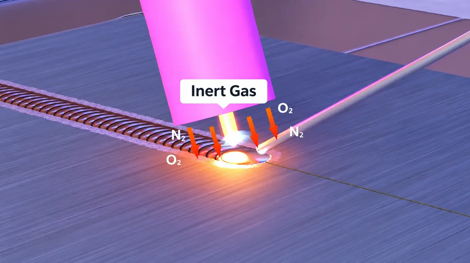
The diagram illustrates shielding-gas coverage, not a universal gas-selection specification. GMAW may use inert gas, active gas, or mixed shielding gas depending on the material, transfer mode, filler, and approved procedure.
A Practical Starting Guide
| Process | Common starting approach | Main process concern | What can change the choice |
|---|---|---|---|
| SMAW | Drag in many flat, horizontal, and overhead applications | Slag behind the leading edge of the puddle | Vertical-up technique, electrode, joint, WPS |
| FCAW | Drag is common | Slag control and sound fusion | Wire type, position, joint, procedure |
| Solid-wire GMAW | Push is common for thin sheet and many pulsed/spray applications | Visibility, shielding gas, heat input, bead profile | Transfer mode, thickness, penetration requirement, access |
| GTAW | Establish from the joint and procedure | Torch control, filler access, heat input, appearance | Material, position, joint, filler method, procedure |
What This Can Change on a Sheet-Metal Enclosure
Push and drag do not decide product quality alone. Welding current, voltage, wire feed, travel speed, fit-up, material thickness, joint design, clamping, and weld sequence can have a larger effect. Still, travel direction can alter the bead profile enough to matter when the finished part has a visible face, a close-fitting door, or a surface that needs coating.
Under comparable solid-wire GMAW conditions:
- A push technique generally tends toward a wider, flatter bead with less penetration.
- A drag technique generally tends toward a narrower bead with more buildup and greater penetration.
Those are tendencies, not guaranteed outcomes. The production choice must match the function of the actual joint.
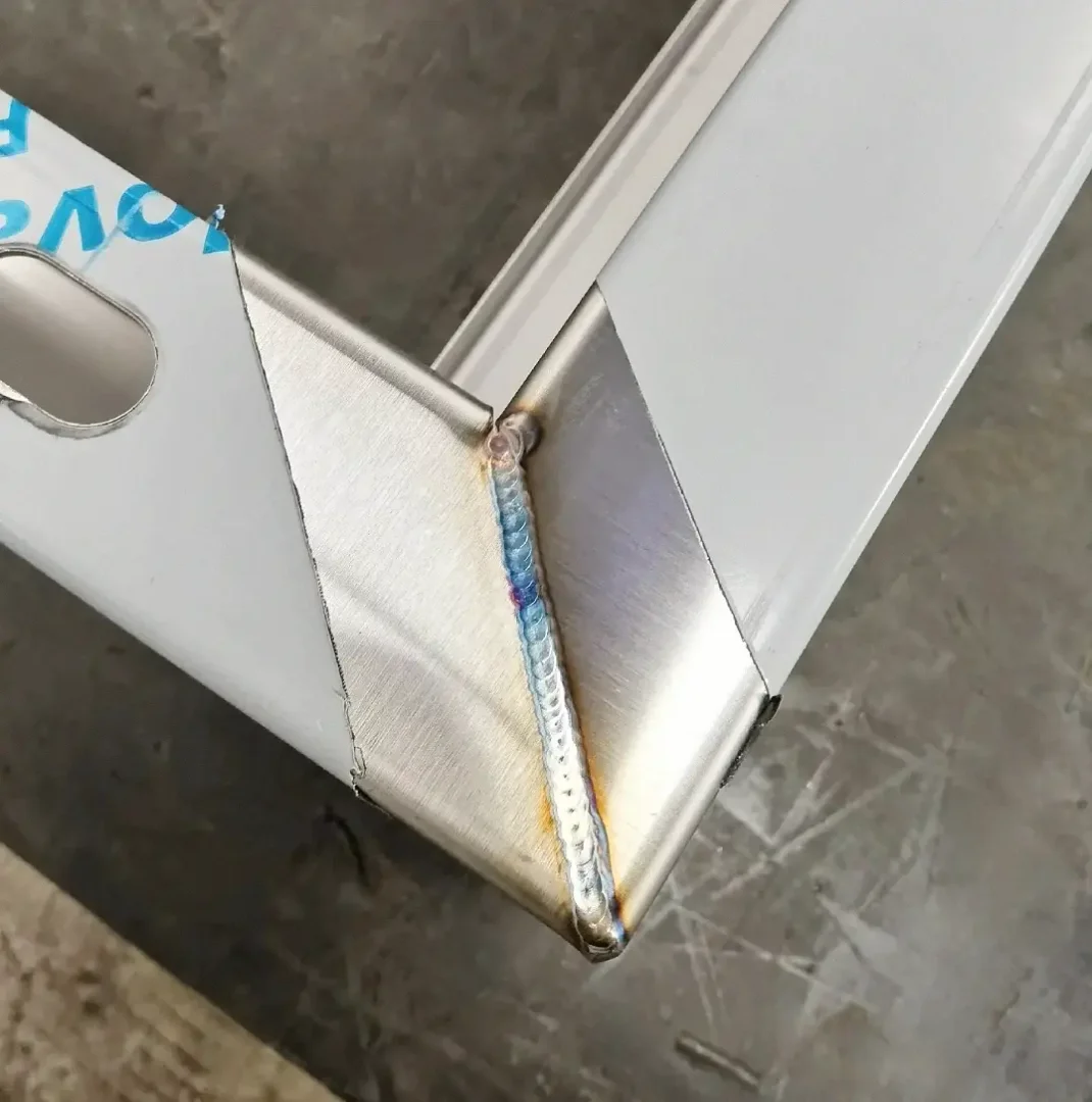
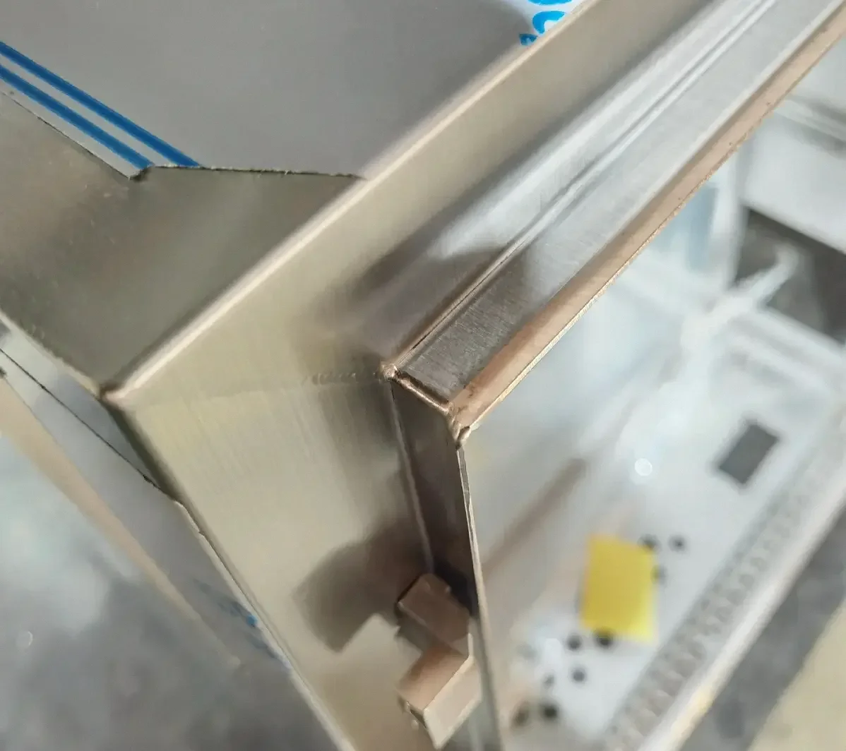
The original fabrication photographs below show raw enclosure-corner details. They are included to show why weld access, visible surfaces, and finishing allowance need to be addressed early. A photograph by itself cannot identify the welding process, prove a travel angle, or establish a finished-weld acceptance standard.
Manufacturing Review: Define the Requirement, Not the Welder's Hand Motion
The two original photographs support a useful drawing-review point: an enclosure corner is not just a weld location. It may also be a visible surface, a coating surface, an assembly interface, or a distortion-sensitive feature.
For a welded cabinet, enclosure, or bracket, the drawing or RFQ should define the product requirement:
- Weld location, length, size, and whether the weld is continuous or intermittent.
- Which surfaces stay visible after grinding, painting, powder coating, or other finishing.
- Sealing, structural, grounding, or assembly-retention function.
- Areas near door openings, gasket lands, threaded hardware, mounting interfaces, and critical assembly datums.
- Required weld profile, finish level, and acceptance criteria.
- Required access for welding, clamping, inspection, grinding, surface preparation, and coating.
The WPS or approved production instruction should define the method: process, wire or electrode, transfer mode, position, travel-angle technique, weld sequence, fixturing, and inspection approach. That separation prevents a drawing from dictating one operator technique while leaving the actual functional requirement unclear.
Questions Worth Resolving Before Production
- What process and position are planned? This determines whether slag control, shielding-gas coverage, or a different issue is the leading concern.
- What must the finished weld do? Define strength, sealing, appearance, grounding, or simple assembly retention.
- What is sensitive near the weld? Check thin material, visible faces, door fit, gasket compression, hardware, coatings, and measurement datums.
- What procedure governs the weld? Confirm the method against the WPS and filler or wire guidance before production.
That sequence is more useful than a blanket instruction to always push or always drag.
FAQ
Should a mechanical drawing specify push or drag welding?
Usually, the drawing should specify the finished weld requirement rather than a universal travel angle. The WPS or approved work instruction controls the welding method when that level of direction is required.
Is push welding always better for thin sheet metal?
No. Push is often useful in solid-wire GMAW on thin sheet, but material thickness, joint design, transfer mode, penetration requirement, access, and the approved procedure can change the choice.
Can a weld photo prove that a push or drag technique was used?
No. A weld photograph can help review access, profile, visible surfaces, and finishing needs, but it cannot reliably prove the welding process or travel angle without supporting production information.
The Takeaway
The memorable rule is simple: slag-forming processes often favor drag; solid-wire GMAW often favors push. The reason is the weld-pool environment, not a contradiction in terminology. For sheet-metal work, turn that knowledge into a clearer RFQ and drawing review—then confirm the actual method through the qualified procedure.