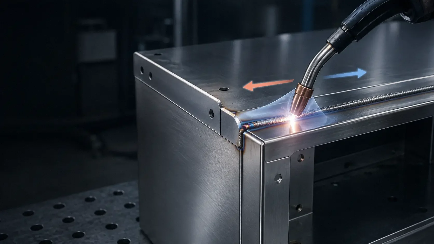

What heat treatment actually changes
Heat treatment is often summarized as heating and cooling steel, but that description misses the useful part. The real objective is to control which phases form, where they form through the section, how fine the microstructure becomes, and how much residual stress or distortion remains when the part returns to room temperature.
Two parts made from the same heat of steel can finish with very different hardness, toughness, machinability, and dimensional stability. The difference can come from austenitizing temperature, soak time, cooling rate, quench severity, section thickness, or the tempering step that follows.
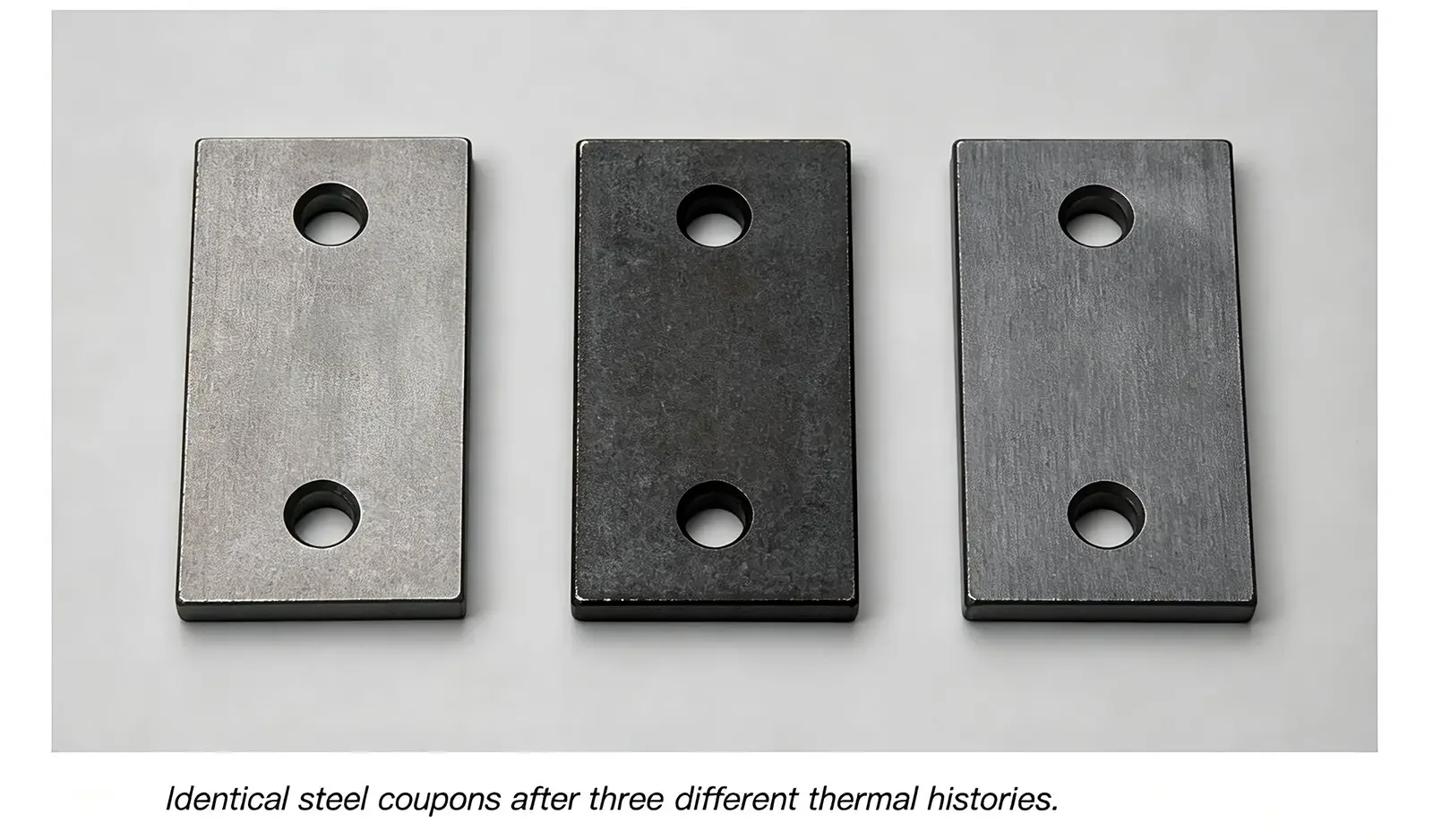
A useful process description therefore needs more than a furnace setpoint. It should identify the material, starting condition, heating range, time at temperature, atmosphere, quench medium and agitation, transfer delay, tempering cycle, and acceptance tests.
1. Start with chemistry, not the furnace
Heat treatment is not alchemy. It rearranges the carbon and alloying elements already present in the steel; it does not create a response that the composition cannot support. Thermochemical surface treatments such as carburizing and nitriding are a separate case because they deliberately change the surface composition.
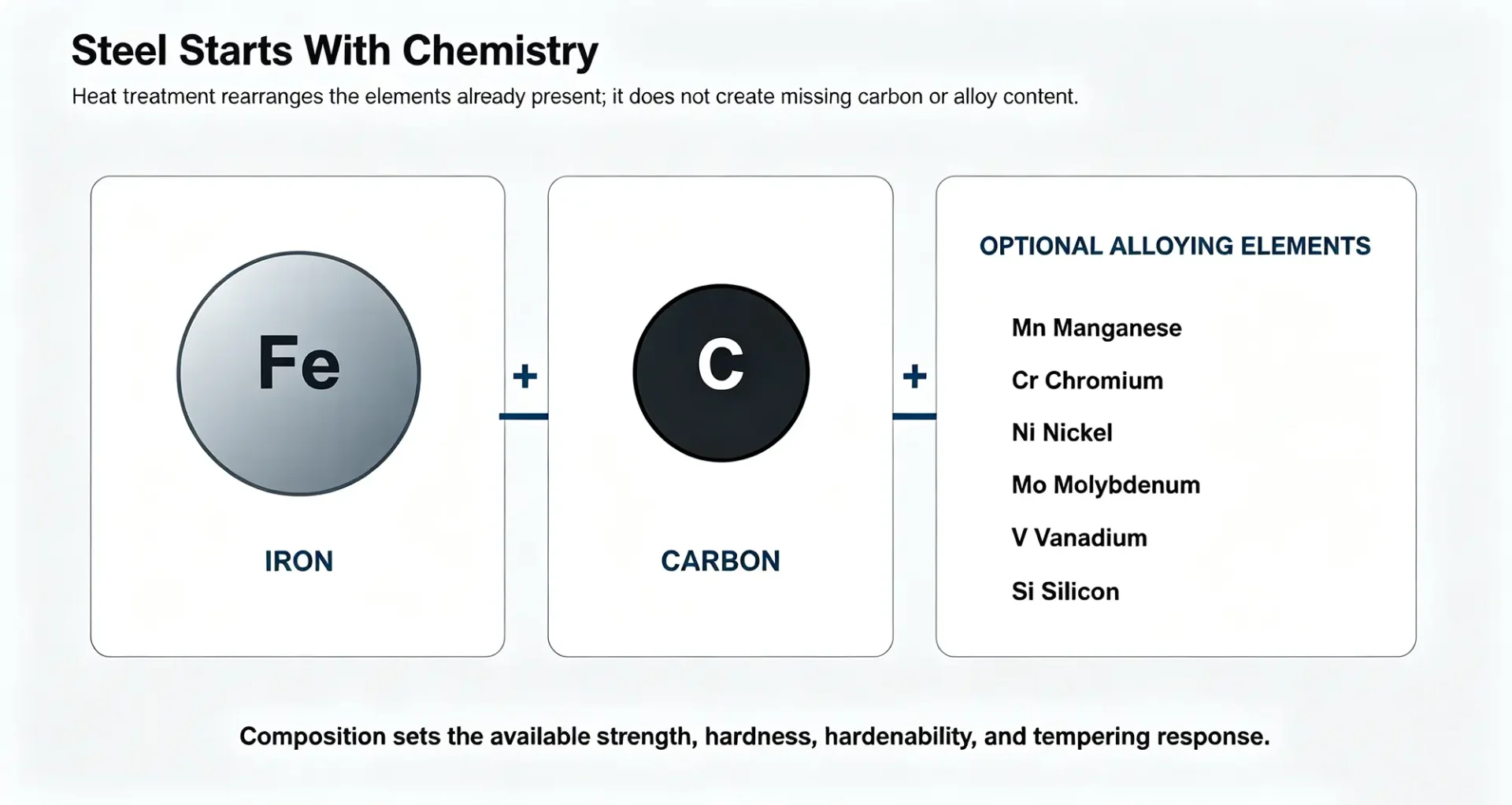
Carbon strongly affects the maximum martensitic hardness that a carbon or low-alloy steel can develop. Alloying elements may increase hardenability, tempering resistance, toughness, corrosion resistance, or combinations of those properties. Their effects are not interchangeable, and the same nominal hardness can hide very different microstructures and performance.
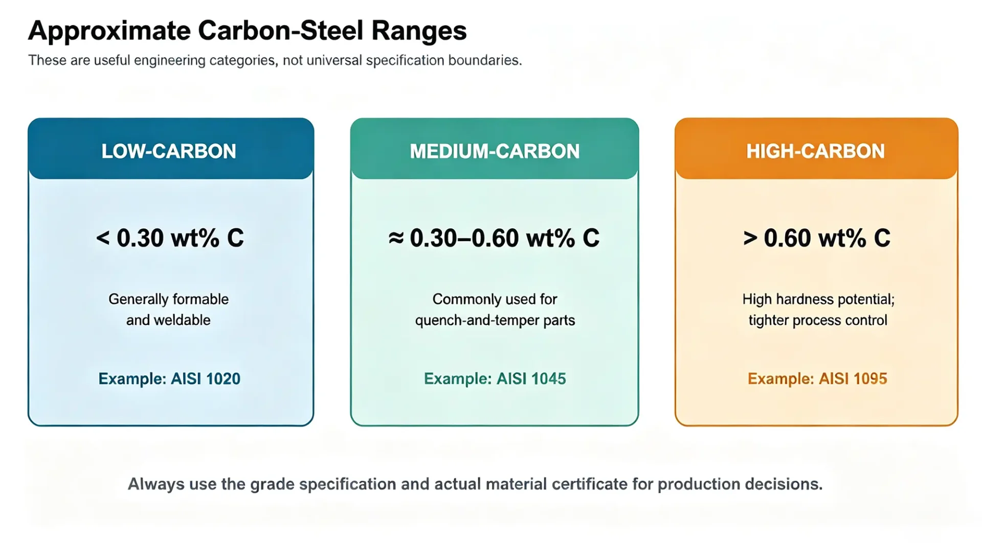
Carbon-steel categories are approximate
Low-, medium-, and high-carbon labels are convenient engineering shorthand, not universal specification boundaries. The grade specification and the actual material certificate take precedence. AISI 1045, for example, is commonly treated as a medium-carbon steel and is often used when a quench-and-temper response is needed, but the attainable depth of hardening still depends on section size and quench conditions.
2. Crystal structure and phase equilibrium
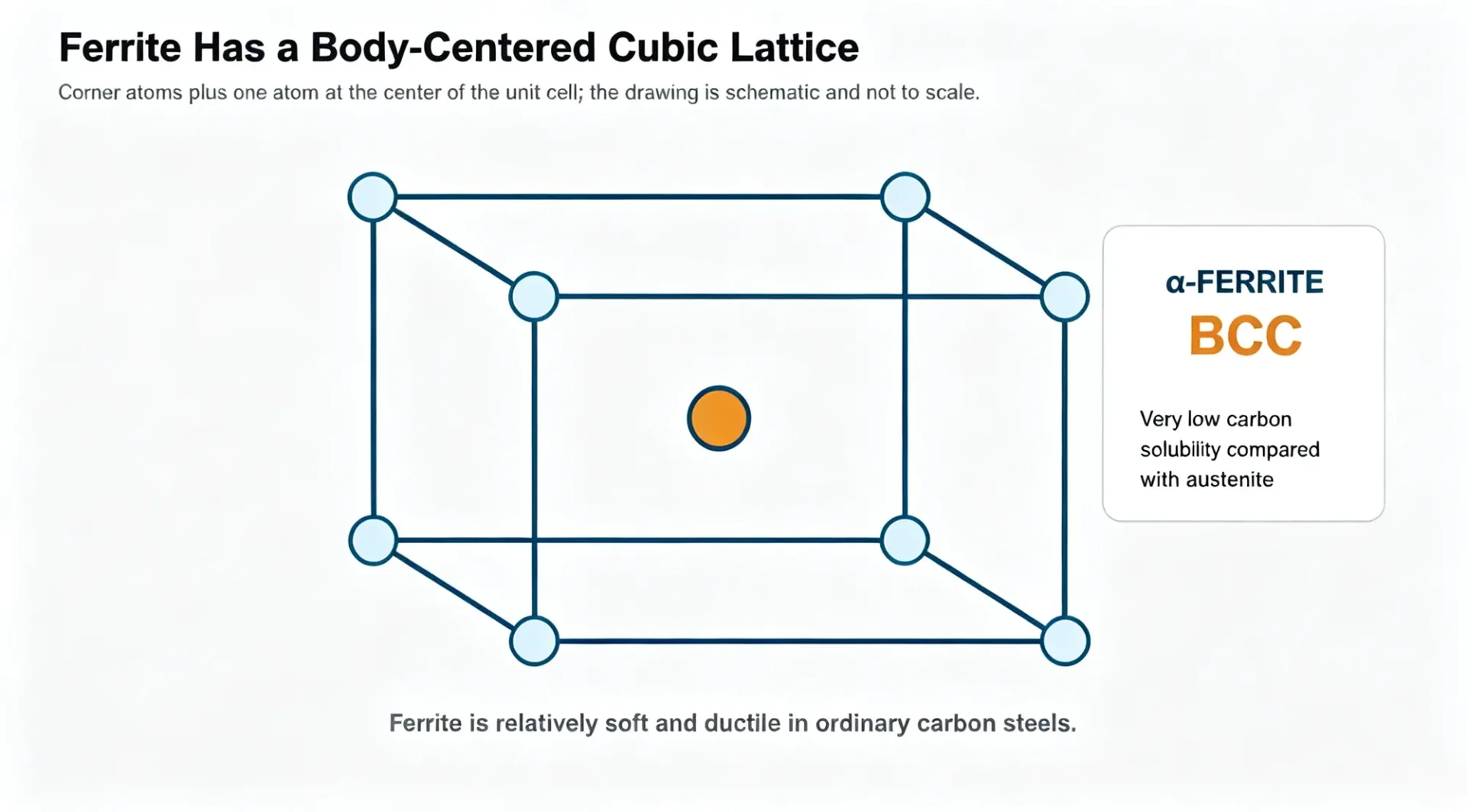
Steel changes because iron can adopt more than one crystal structure. At ordinary temperatures, ferrite has a body-centered cubic structure. It is relatively soft and ductile and can dissolve only a small amount of carbon. Austenite, stable over a higher temperature range, has a face-centered cubic structure and can hold much more carbon in solid solution.
Pure iron is a reference point, not a steel recipe
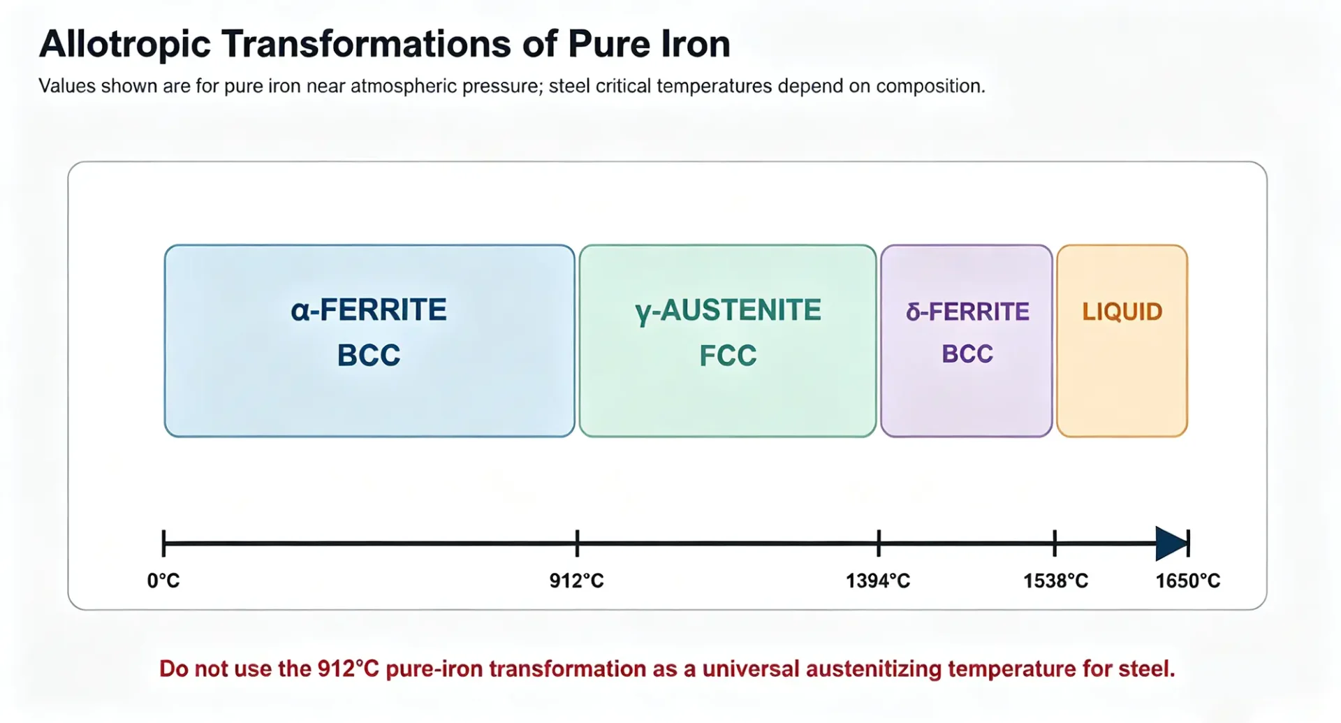
Near atmospheric pressure, pure iron is alpha ferrite below about 912°C, gamma austenite from about 912°C to 1394°C, delta ferrite from about 1394°C to the melting point near 1538°C, and liquid above that point. Carbon and alloying elements shift the critical temperatures, so 912°C should never be treated as a universal austenitizing temperature for steel.
Use the iron–cementite diagram as a map
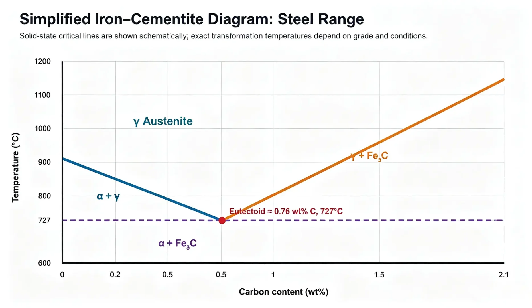
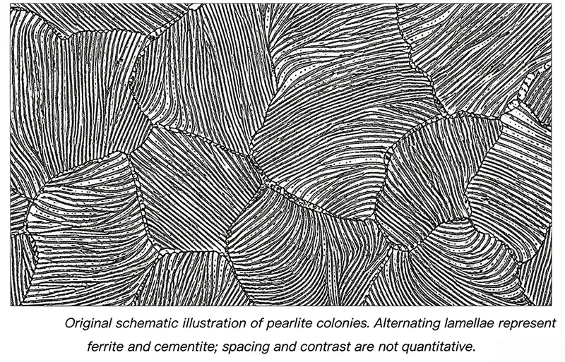
The iron–cementite phase diagram shows equilibrium relationships between temperature and carbon content. In the steel range, the eutectoid point is commonly shown near 0.76 wt% carbon and 727°C. On slow cooling near this composition, austenite transforms to pearlite, a lamellar mixture of ferrite and cementite.
The diagram is a map of possible equilibrium phases, not a time-based process schedule. It does not tell you how quickly transformation occurs, whether a thick section cools uniformly, or whether the actual path produces pearlite, bainite, martensite, or a mixture.
Carbon solubility explains why austenitizing matters
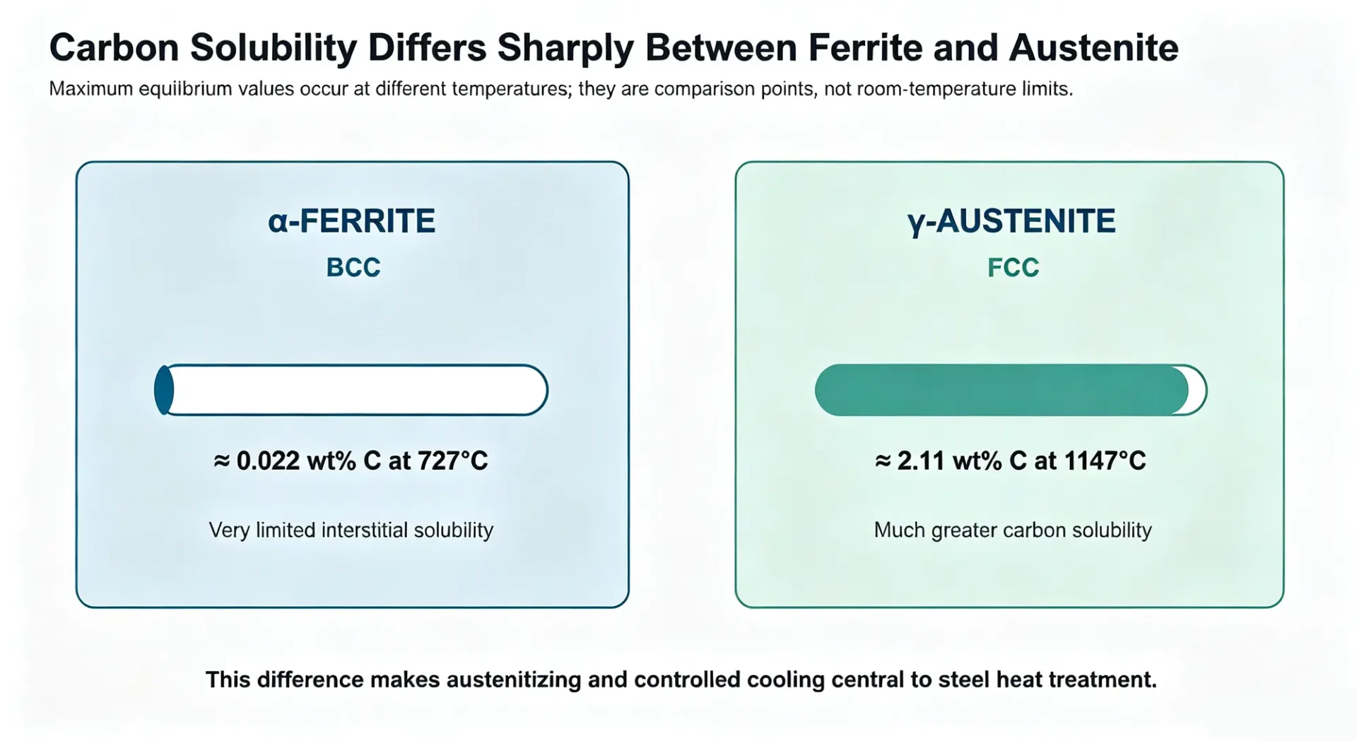
Ferrite can dissolve only about 0.022 wt% carbon at 727°C, while austenite can dissolve roughly 2.11 wt% carbon at 1147°C. Those are maximum equilibrium values at different temperatures, not room-temperature solubility limits. The contrast is what allows carbon to redistribute during austenitizing and then become partitioned, precipitated, or trapped as the steel cools.
3. Time and cooling rate determine the transformation path
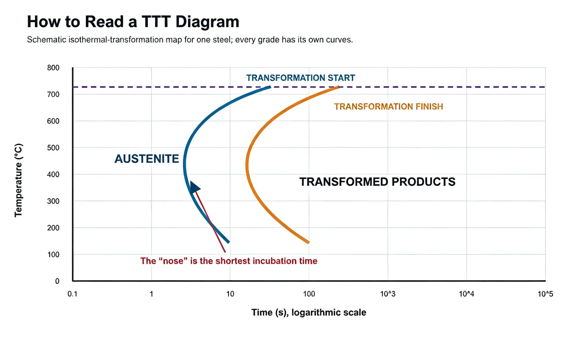
Phase diagrams answer what is stable at equilibrium. Heat-treatment decisions also need kinetics: how long transformation takes and what happens during a real cooling path. Time–temperature–transformation diagrams describe isothermal behavior after austenitizing. Continuous-cooling-transformation diagrams describe transformations during continuous cooling and are usually closer to production quenching or air cooling.
Reading a TTT diagram
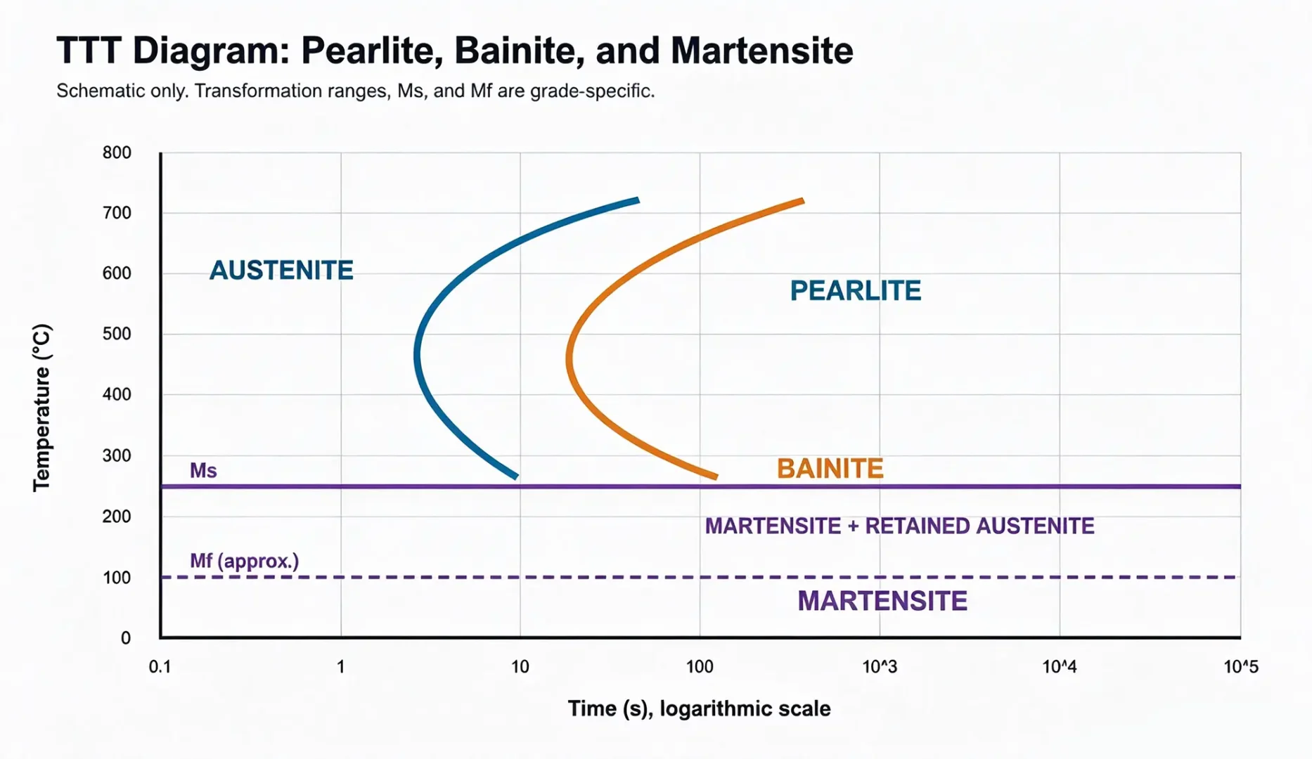
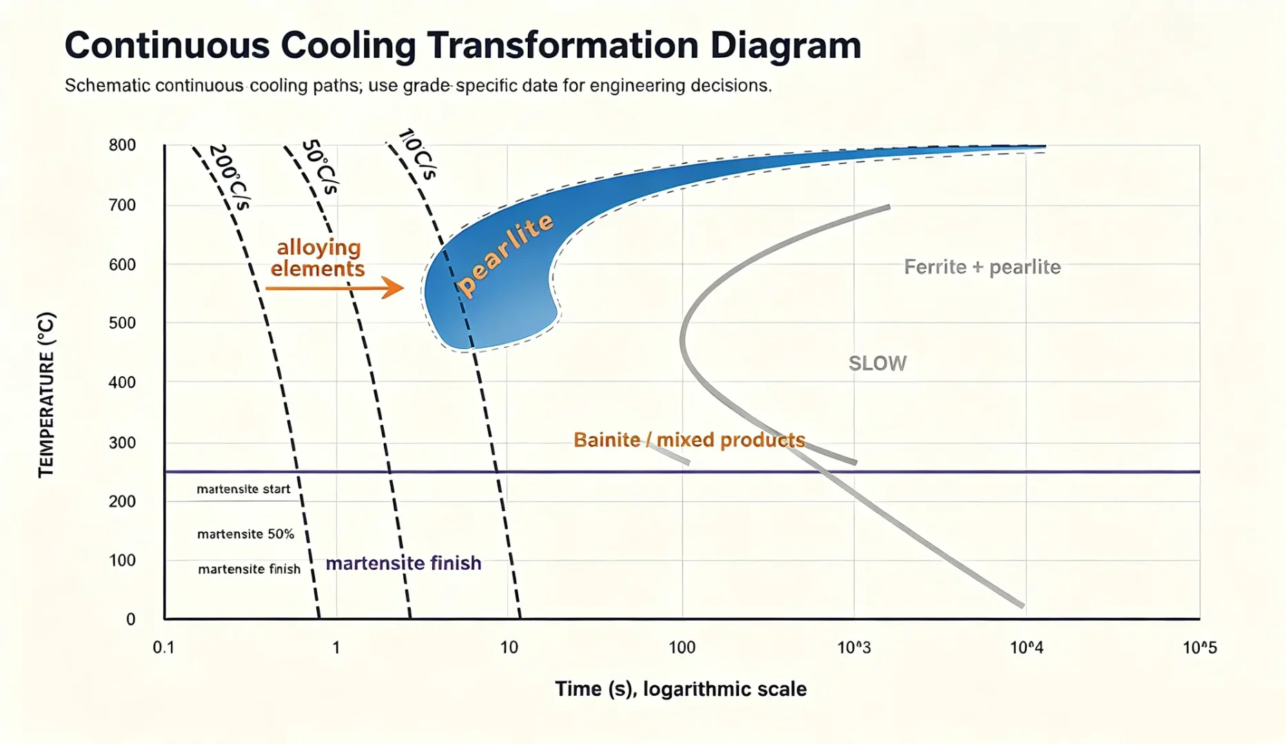
A typical TTT diagram has start and finish curves. The leftmost point of the start curve is often called the nose because it represents the shortest incubation time for a diffusional transformation. A cooling path intended to produce mostly martensite must avoid entering the relevant ferrite, pearlite, or bainite transformation region before reaching the martensite-start temperature.
Martensite is hard because carbon is trapped
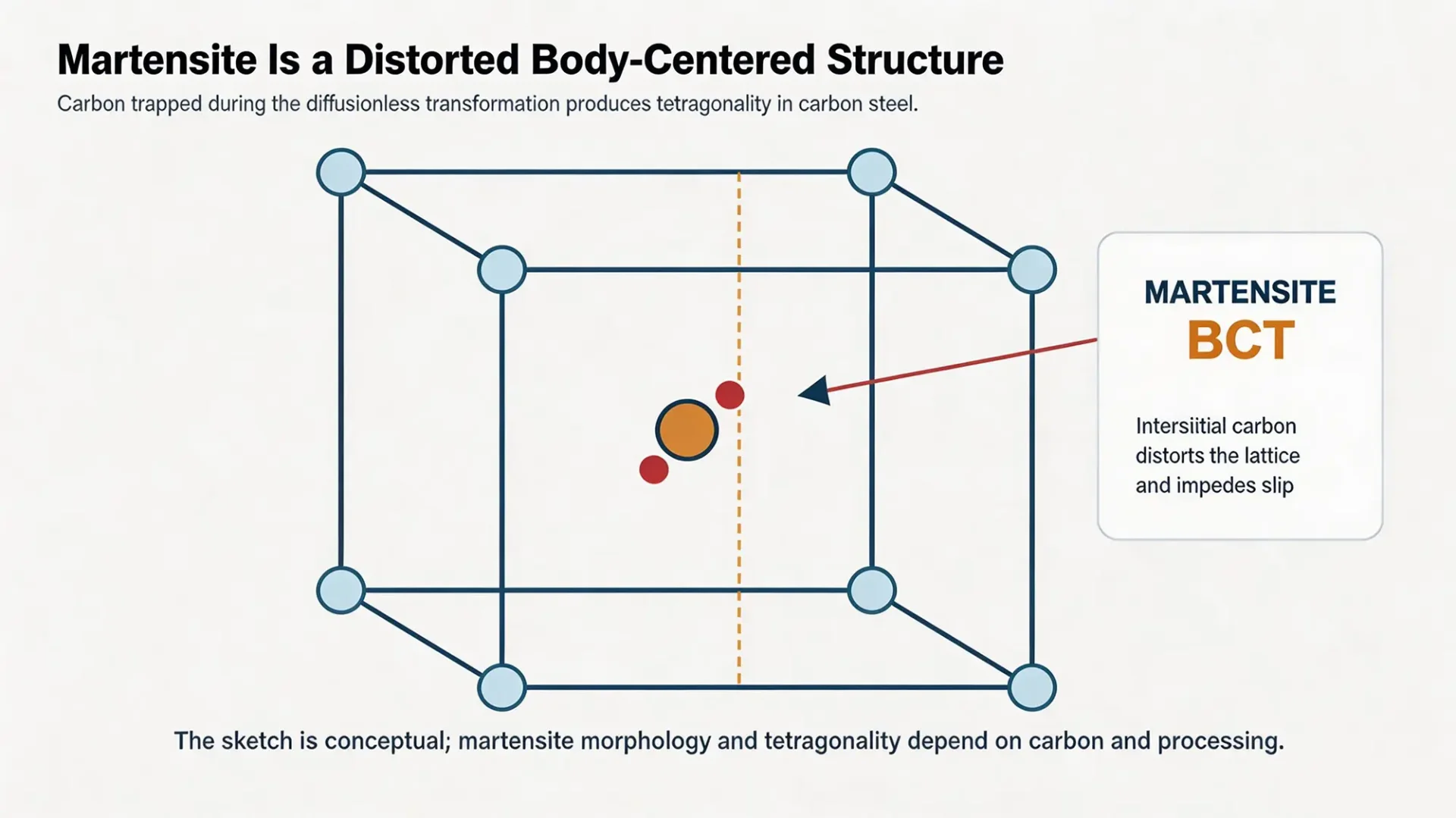
Martensite forms by a diffusionless transformation. The iron lattice changes rapidly while carbon does not have time to redistribute over long distances. In carbon steel, the trapped carbon produces a body-centered tetragonal distortion and makes dislocation motion difficult. The result can be very high hardness, along with high internal stress and limited toughness in the as-quenched condition.
Martensite formation is not the end of the process for most engineering parts. Quenched steel is commonly tempered soon afterward to reduce brittleness, relieve some stresses, and tune the final hardness–toughness balance.
CCT diagrams are closer to real cooling
A CCT diagram overlays continuous cooling paths on transformation regions. A fast path may avoid diffusional transformation and produce mostly martensite. A moderate path may cross regions that form bainite or mixed products. A slow path can produce ferrite and pearlite. The labels are not guarantees: the actual path at the center of a large part can be much slower than the path near the surface.
4. Four foundational heat-treatment paths
The names annealing, normalizing, quenching, and tempering describe different thermal intentions. They should not be reduced to a single temperature or a generic furnace cycle.
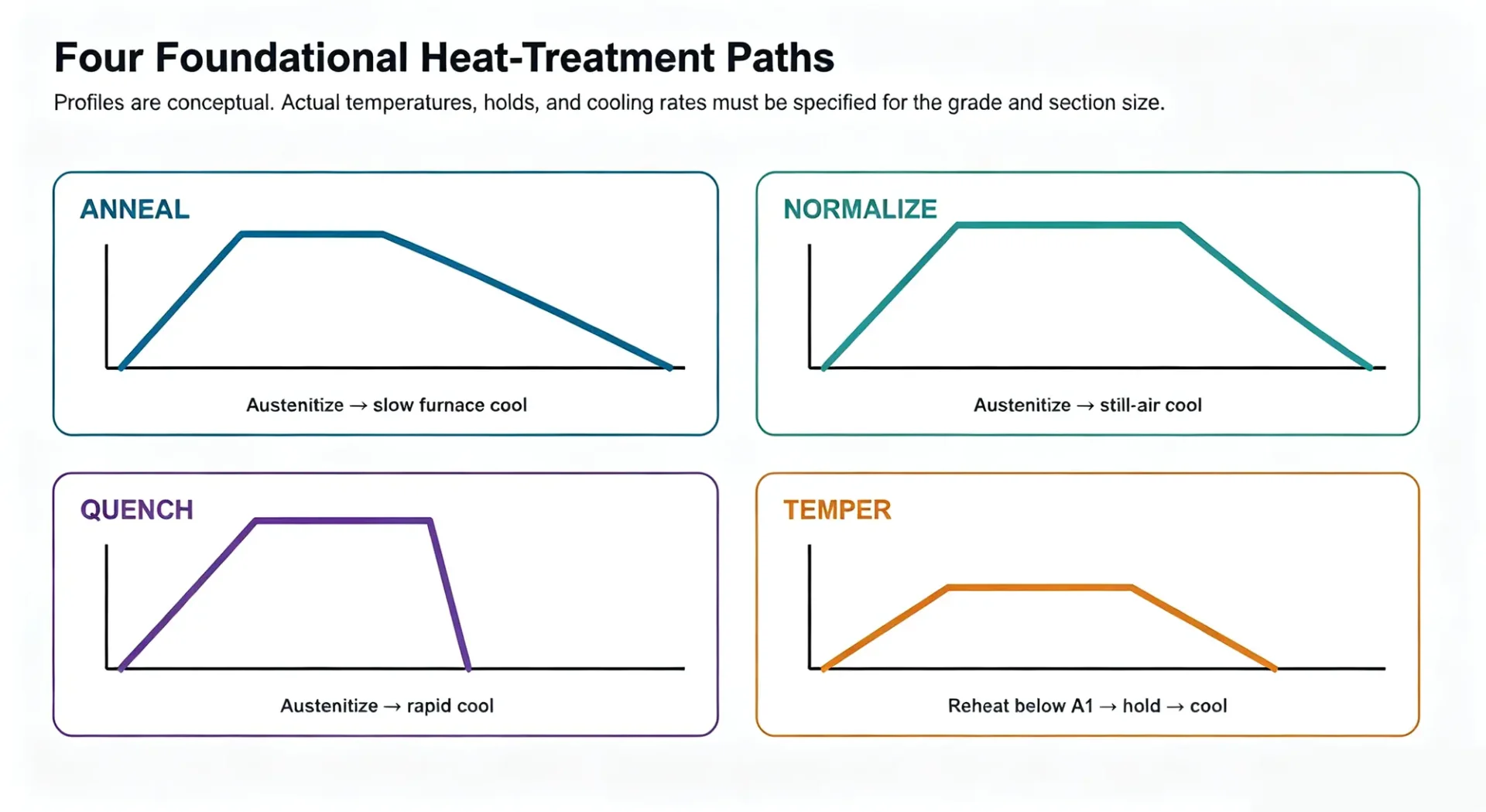
Annealing. A full anneal generally uses slow furnace cooling to produce a softer, more machinable condition. Other annealing treatments have different goals, so the term should be qualified in a process specification.
Normalizing. The part is heated into the appropriate austenitic range and cooled in still air. Compared with a full anneal, the faster cooling commonly produces a finer structure and somewhat higher strength.
Quenching. Rapid cooling aims to suppress diffusional products and form martensite through the required depth. Water, polymer, oil, gas, and interrupted quench methods differ in severity, uniformity, fire risk, distortion, and crack risk.
Tempering. Tempering reheats hardened steel below the lower critical temperature, holds it, and cools it under controlled conditions. Higher tempering temperatures generally reduce hardness and strength while improving toughness and dimensional stability, but the response depends on grade and time.
5. Hardenability is not the same as hardness
Hardness is a measured resistance to indentation under a defined test method. Hardenability describes how deeply a steel can develop a hardened structure under a given cooling condition. Two steels with similar carbon content may reach similar maximum surface hardness, yet one may maintain high hardness much farther from the quenched surface because its alloy content delays diffusional transformation.
What the Jominy end-quench test shows
ASTM A255 uses a standardized 25.4 mm diameter by 101.6 mm long specimen for the end-quench method. One end is water-quenched, a flat is ground, and hardness is measured at specified distances from the quenched end. A slowly declining hardness curve indicates higher hardenability; a steep decline indicates that hardness is lost more quickly as cooling rate decreases with distance.
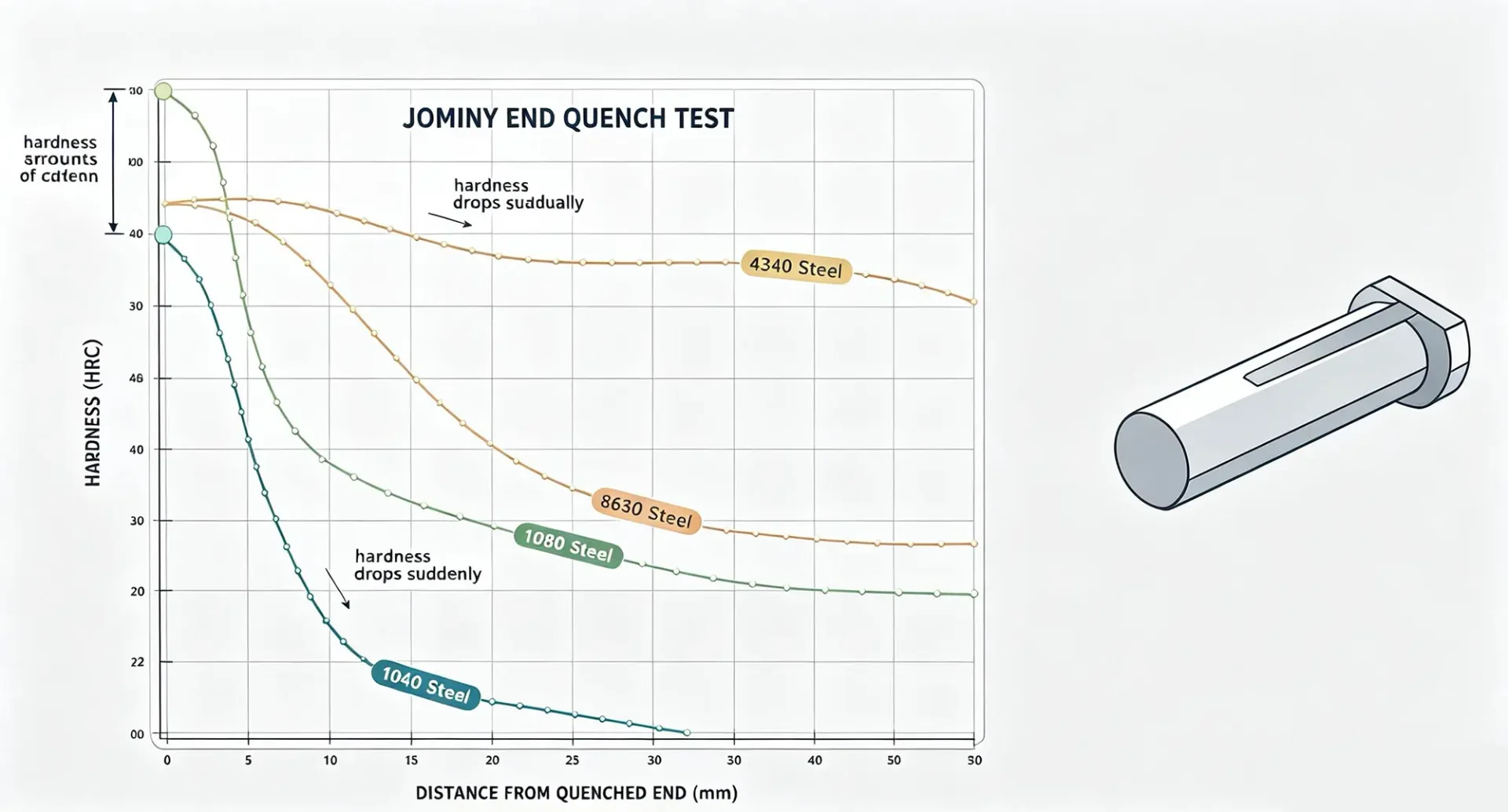
The test does not directly predict every production section. Geometry, quench agitation, bath temperature, surface condition, transfer time, and furnace history still matter. Jominy data are best used with section-size correlations, simulation, or validated shop experience.
6. Surface hardening can separate wear and core requirements
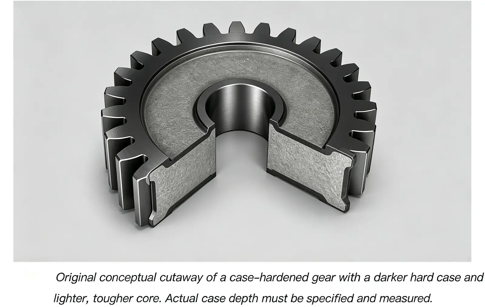
A through-hardened part is not always the best answer. Gears, shafts, and wear components often benefit from a hard surface over a tougher core. The route depends on the alloy and the required case depth.
Induction and flame hardening transform an existing carbon-rich surface by rapid local heating and quenching; they do not add carbon. Carburizing adds carbon at elevated temperature before hardening. Nitriding introduces nitrogen and usually operates below the austenitizing range, which can reduce distortion compared with a quench-based case-hardening process. These methods are not interchangeable.
7. Connect the heat-treatment plan to the full manufacturing route
Heat treatment interacts with forging, casting, machining, grinding, coating, and final inspection. A process that meets hardness on a coupon can still fail on a real part if distortion removes grinding allowance, decarburization reduces surface hardness, a sharp corner cracks during quenching, or the center cools too slowly.
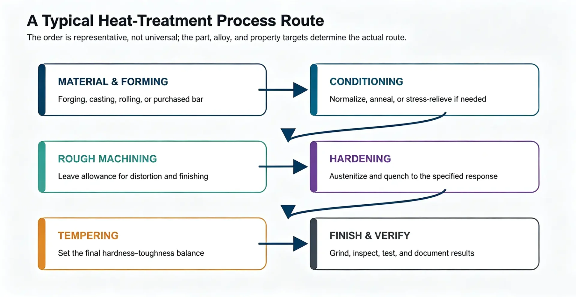
A production traveler should make the sequence explicit. It should also identify where material identity, furnace uniformity, atmosphere, quench condition, hardness, case depth, microstructure, distortion, and crack inspection are checked. The right checkpoints depend on the consequence of failure and the drawing requirements.
Common mistakes to avoid
- Using austenitizing temperature as a generic steel constant. Critical temperatures depend on composition and starting condition; use the grade-specific process range.
- Treating surface hardness as proof of through-hardening. Measure or infer the hardness profile at the required depth.
- Calling every rapid cool a quench without defining the medium and conditions. Agitation, concentration, bath temperature, and transfer delay can materially change the result.
- Skipping tempering after martensitic hardening. Delays can increase crack risk, and untempered martensite is rarely an acceptable final condition for loaded parts.
- Using a generic TTT or CCT diagram for another grade. Even nominally similar steels can have different transformation behavior because of chemistry, grain size, and prior processing.
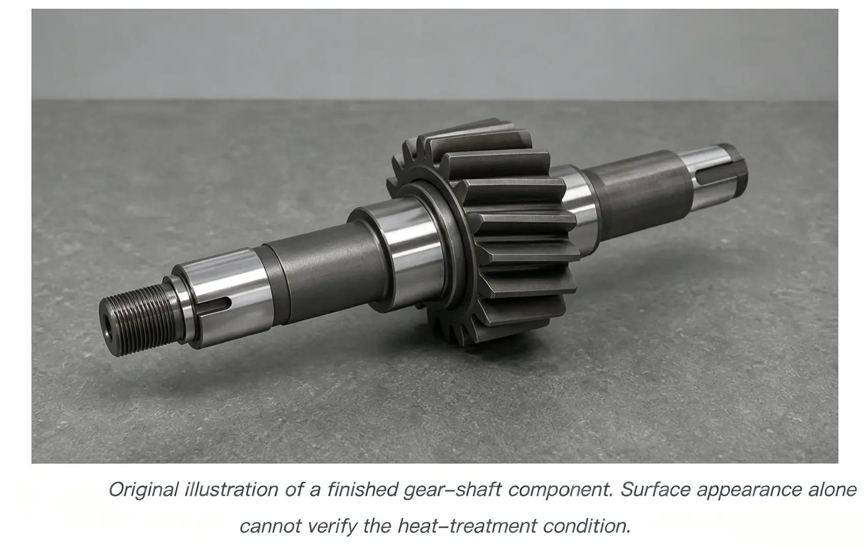
- Assuming color proves heat treatment. Oxide color depends on atmosphere, surface finish, contamination, and handling; verify properties with defined tests.
Frequently asked questions
Does higher hardness always mean better performance?
No. Higher hardness can improve wear resistance and strength, but it may reduce toughness and increase sensitivity to cracks, grinding damage, and impact loading. The target should come from the service condition, not a general preference for the highest possible number.
Why can two parts from the same batch have different hardness?
Section thickness, furnace loading, temperature uniformity, transfer time, surface condition, quench flow, part orientation, and local agitation can all change the cooling path. Material chemistry also varies within permitted limits.
Can AISI 1045 be through-hardened?
It can develop a useful quench-and-temper response, especially in smaller sections, but its hardenability is limited compared with many alloy steels. Whether the center reaches the required structure depends on section size, geometry, and quench severity.
What is the safest way to choose a heat-treatment cycle?
Start with the drawing and the material specification. Then use supplier recommendations, current standards, grade-specific transformation data, section-size analysis, furnace and quench capability, and a validation run with the required tests. A blog diagram is useful for understanding the mechanism, not for releasing a production lot.
Final takeaway
Steel heat treatment works because composition, crystal structure, time, temperature, and cooling rate interact. Chemistry defines the available response. Austenitizing establishes the starting austenite. Cooling selects pearlite, bainite, martensite, or a mixture. Tempering then adjusts the hardened structure toward the required balance of hardness, strength, toughness, and stability.
The most reliable process descriptions connect those metallurgical ideas to real controls: material identity, section size, furnace uniformity, atmosphere, quench condition, transfer time, tempering, and verification. That is what turns a thermal cycle into a repeatable manufacturing process.