
A liquid‑cooling loop can meet its thermal target and still fail at the rack. Rear connectors end up behind a PDU, a manifold bracket flexes during service, or a drip tray makes the fittings impossible to inspect.
Those are enclosure problems, not coolant problems. From our fabrication experience reviewing RFQ documents, many well‑defined thermal requirements skip critical sheet‑metal interface details. A workable liquid‑cooled AI rack enclosure starts by locking in the heat‑transfer boundary and maintenance sequence before finalizing sheet‑metal gauge selections.
|
Three corrections to common liquid-cooling claims •PUE is a data-center metric. A rack, cold plate, or coolant loop does not carry a fixed PUE value. The site boundary, climate, load, controls, and electrical system all affect the result. •There is no universal rack-kW cutoff. The server requirement, residual air load, facility temperatures, redundancy, and service model determine whether air, cold plates, a rear-door exchanger, or immersion makes sense. •“Liquid cooled” is not a complete interface. Drawings need a named technology cooling system, coolant, flow and pressure limits, connections, service direction, and ownership split. |
1.Start With the Heat‑Transfer Boundary
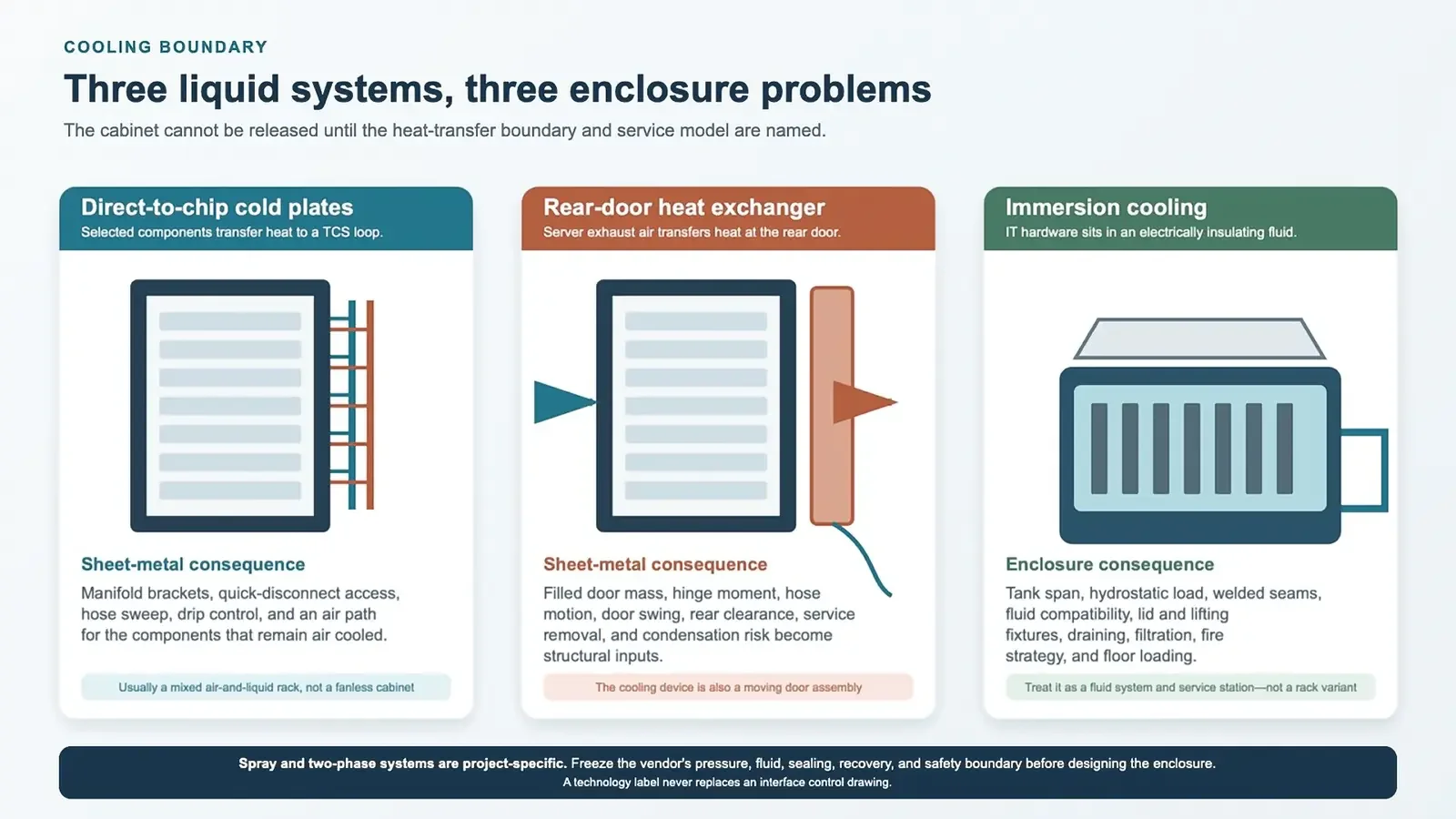
The original idea—cold plate, immersion, or spray—is directionally useful, but it is not enough for an enclosure RFQ. Each method moves heat across a different physical boundary, and that boundary decides what the sheet metal has to support.
Cold plates usually leave a residual air load
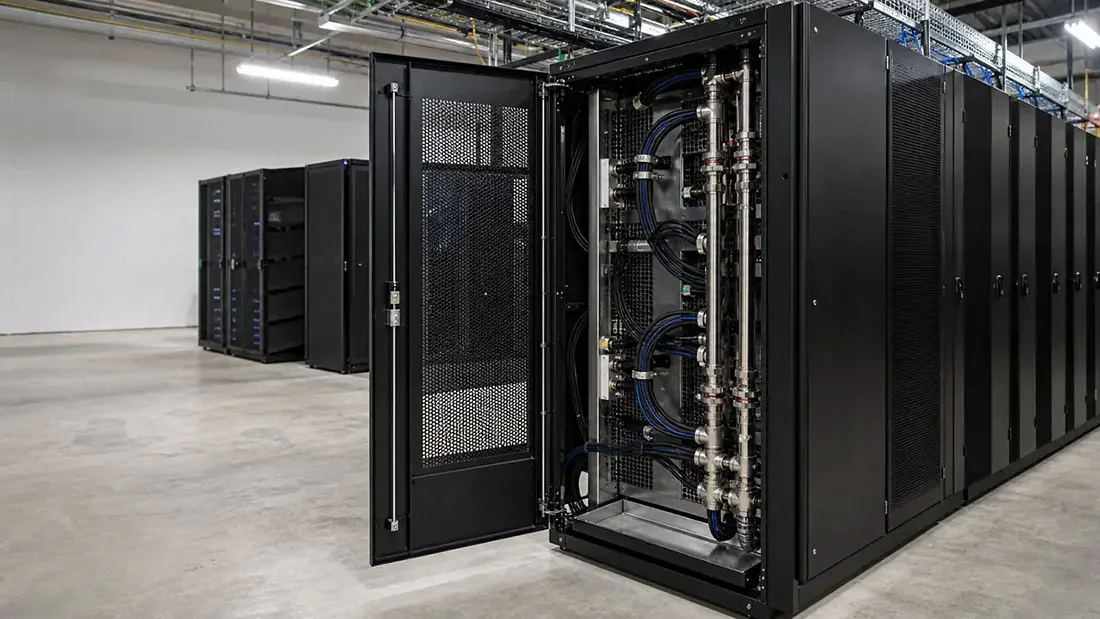
Direct‑to‑chip (D2C) cooling puts cold plates on named devices such as CPUs, GPUs, or memory. A rack manifold feeds the server loops through hoses and quick disconnects.
Even with liquid cooling in place, power supplies, storage, networking, voltage regulators, and components that were not included in the liquid path may still depend on airflow.
Ask the server supplier for the liquid heat‑capture fraction and the remaining air‑side requirement at the intended workload. Without those two numbers, removing perforated doors or reducing fan capacity is guesswork.
A rear‑door exchanger turns cooling into a moving load
A rear‑door heat exchanger transfers server exhaust heat to liquid at the cabinet boundary. The server remains air cooled, but the rear door becomes a filled heat exchanger with hoses. Hinge moment, latch load, door sag, hose motion, service swing, removal equipment, and condensate risk now belong in the mechanical specification.
Immersion and spray systems need a different enclosure definition
Immersion places the hardware in an electrically insulating fluid. Single‑phase systems keep the fluid liquid; two‑phase systems add boiling, condensation, and vapor‑management requirements. Either way, this is a tank and fluid‑handling system, not a conventional rack with extra plumbing.
Spray cooling and other directed‑fluid systems can be valid, but they are more supplier‑specific. Nozzle pressure, droplet containment, recovery, filtration, sealing, and the service procedure must be frozen before the enclosure can be designed. We would not treat “spray cooled” as a standard rack category on its own.
|
Cooling method |
Heat-transfer boundary |
Residual air |
Main enclosure work |
|
D2C cold plate |
Selected devices to a TCS loop |
Usually remains |
Manifold brackets, QDs, hoses, drip path, mixed air/liquid service |
|
Rear-door heat exchanger |
Server exhaust air to liquid at the rear door |
Air still crosses the server |
Door structure, hinges, hoses, rear clearance, condensation control |
|
Immersion |
Hardware directly to dielectric fluid |
Not a conventional rack path |
Tank, lid, lifting, welds, drainage, fluid and floor-load strategy |
2.Turn a Cold‑Plate Loop Into Serviceable Rack Hardware
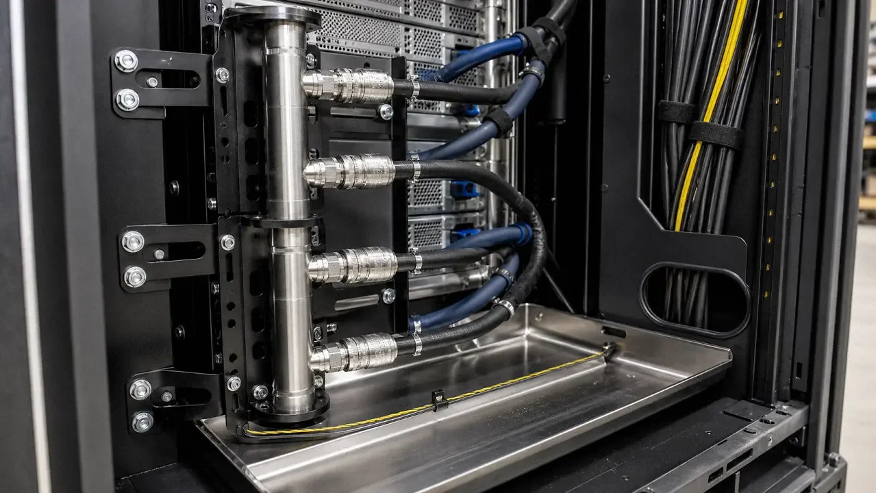
A rack manifold is not a late‑stage accessory. Once it is filled and connected, the support sees static weight, mating force, hose pull, pressure transients, shipping vibration, and thousands of service actions over the system life.
Give the manifold a datum, stiffness, and an exit path
OCP guidance calls for a rack mounting plate or bracket, uniform flow distribution, suitable quick disconnects, a high‑point vent, and a low‑point drain. For fabricated brackets, 2.0–3.0 mm formed steel or stainless is a useful quoting range. It is only a starting point. The filled manifold mass, connector force, blind‑mate tolerance stack, vibration, and bracket span set the final section.
Slotted adjustment can absorb rack and manifold build variation, but it should not leave the assembly free to drift. Use a fixed datum in one direction, controlled adjustment in the others, and a repeatable torque method. If the server uses blind‑mate QDs, the connector supplier's float and alignment envelope overrides a generic rack tolerance.
Protect the hose without hiding the fitting
The rear of the rack gets crowded fast. A common pitfall we see is assigning the manifold, vertical PDU, fiber manager, copper cables, and door stiffener to the same corner. Each part fits in isolation; the technician's hand does not.
Model the QD mating stroke, hose minimum bend radius, removal direction, torque‑tool access, and the largest cable bundle in the same CAD assembly. Use grommets or rolled edges where a hose can contact sheet metal. Restraints should prevent abrasion and connector side‑load without clamping the hose flat.
Use the drip tray as detection, not concealment
A 1.0–1.5 mm Type 304 stainless tray is a practical starting point for many racks. Formed edges add stiffness, and a removable design makes cleaning easier. If the tray drains by gravity, define the fall, outlet, and blocked‑drain condition. A leak‑detection cable should sit where a small release reaches it without being crushed by service hardware.
The tray should not cover QDs, valve stems, labels, or inspection points. It also needs a removal path after the rack is populated. That sounds obvious, but it is easy to lose when the tray is added after the manifold layout is already fixed.
|
Freeze these interfaces before releasing the rear frame •Manifold: supply/return orientation, mounting datum, filled mass, isolation, vent, drain, removal direction, and connection forces. •Quick disconnects: hand-mate or blind-mate type, keying, sealing material, mating envelope, drip performance, tool access, and replacement method. •Coolant and materials: the approved wetted-material list for manifold, QDs, seals, hoses, valves, cold plates, and any treatment chemicals. •Air side: residual heat load, required airflow, door pressure drop, cable blockage, and shutdown response. •Ownership: which supplier pressure-tests, flushes, caps, ships, fills, commissions, and signs the final loop record. |
3.Treat Immersion Cooling as a Tank Project
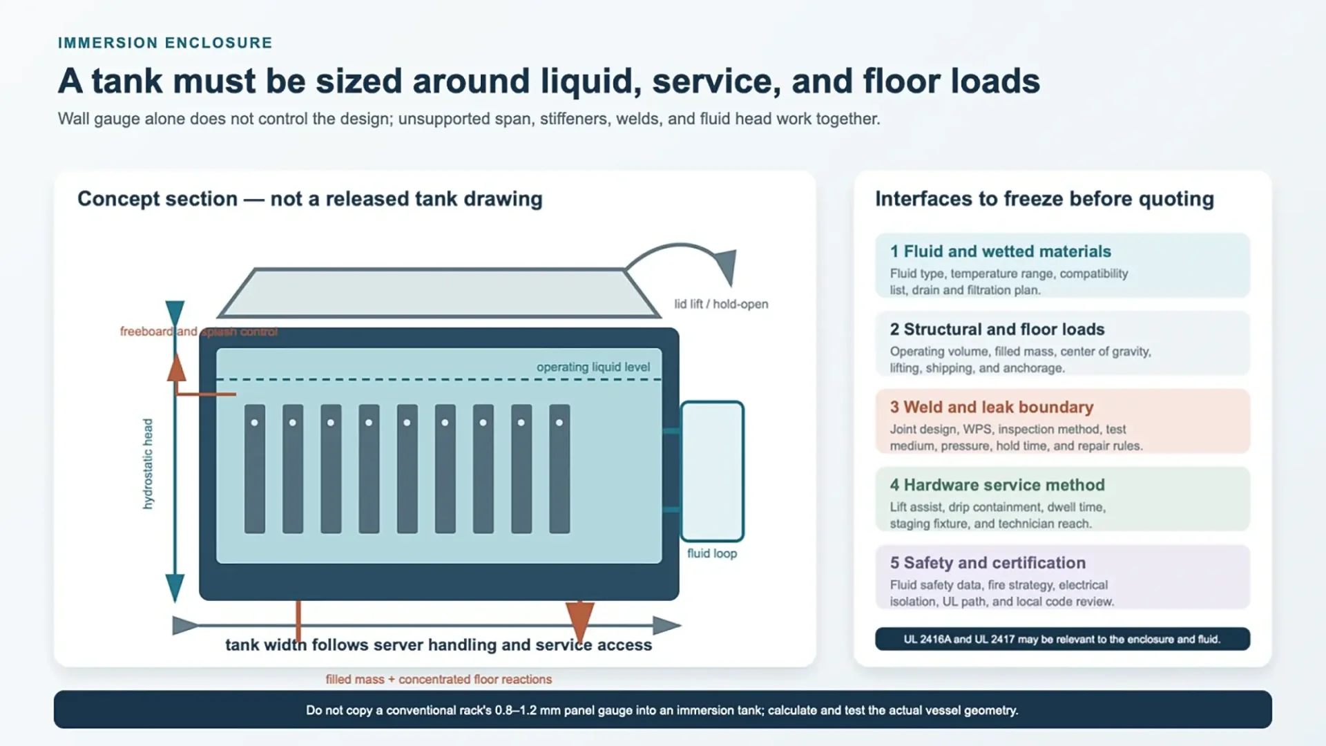
Immersion changes the enclosure more than any other liquid‑cooling option. The hardware orientation changes, the fluid becomes part of the operating mass, and routine service may require lifting a wet server into a drip‑controlled staging fixture.
Hydrostatic pressure is low, but the panel area is large
At the bottom of a tank, static liquid pressure follows p = ρgh. As a planning example, 0.7 m (27.6 in.) of fluid with a density of 800 kg/m³ produces about 5.5 kPa (0.80 psi) at the bottom. That does not sound severe, yet it acts across broad sheet‑metal panels and can create visible bowing or weld distortion.
The same example makes the floor‑load issue clear: 800 L of fluid at 0.8 kg/L adds roughly 640 kg (1,411 lb) before the servers, tank, heat exchanger, pumps, lid, and service fixture are counted. Shipping loads and seismic or anchorage cases are separate again. Tank wall thickness therefore has no useful universal value; unsupported span, stiffener spacing, joint geometry, material grade, and the verification plan decide it.
|
Example calculation—useful for scoping, not for release Fluid density: 800 kg/m³; operating depth: 0.7 m; volume: 800 L. Bottom static pressure: ρgh ≈ 800 × 9.81 × 0.7 = 5.5 kPa (0.80 psi). Fluid mass: 800 L × 0.8 kg/L ≈ 640 kg (1,411 lb). The released design still needs the real fluid properties, panel spans, fill level, dynamic loads, weld details, temperature range, floor interface, and test method. |
Design the lid and service fixture with the tank
The lid needs a safe opening force, a positive hold‑open method, and clearance for overhead lifting or the selected service arm. Show where a wet server dwells, drains, and moves after removal. If the maintenance path crosses an aisle, include the fixture envelope and floor reactions in the layout—not just the closed tank footprint.
Freeboard, splash control, filtration access, fill and drain points, and a way to remove sediment all need defined locations. A clean top view is not enough; the service section drawing is usually where conflicts appear.
Fluid selection is a material and safety decision
Immersion fluid does not automatically prevent oxidation or extend every component's life. Cable jackets, labels, adhesives, elastomers, conformal coatings, plastics, solder masks, and metals can respond differently over time. Require a compatibility list and aging evidence for the actual hardware.
UL 2417 evaluates properties such as autoignition temperature, flash point, and dielectric breakdown for immersion‑cooling fluids. UL 2416A addresses immersion‑cooling cabinets and enclosures. The certification path, local fire review, fluid safety data, electrical isolation, and spill response should be agreed before tank fabrication.
4.Choose Materials Around the Load Path and the Wet Zone
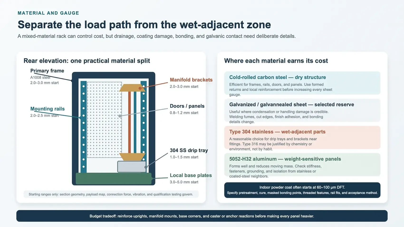
A dry indoor rack does not need to be stainless from top to bottom. ASTM A1008 cold‑rolled steel is a practical baseline for frames, rails, doors, and panels. ASTM A653 galvanized or galvannealed sheet can add corrosion reserve in selected areas. Type 304 stainless works well for drip trays and wet‑adjacent brackets, while 5052‑H32 aluminum can reduce door or panel mass when stiffness and mixed‑metal joints are handled properly.
The ranges below are design‑review starting points for custom fabricated racks. They are not dimensions required by ASTM, IEC, or OCP. Section shape, payload, rail reaction, bracket span, fastener spacing, forming limits, and testing can move every number.
|
Component |
Starting material |
Typical starting thickness |
What drives the final choice |
|
Frame uprights and crossmembers |
ASTM A1008 steel |
2.0–3.0 mm |
Section depth, torsion, payload map, weld or bolt joints |
|
Mounting rails |
A1008 or coated steel |
2.0–2.5 mm |
Cage-nut fit, hole quality, rail reaction, full-height alignment |
|
Doors and removable panels |
A1008, A653, or 5052-H32 |
0.8–1.2 mm |
Perforation, hems, handling, oil-canning, hinge load, finish |
|
Manifold brackets |
Coated steel or Type 304 SS |
2.0–3.0 mm |
Filled mass, QD forces, vibration, adjustment, corrosion exposure |
|
Base and local reinforcement |
A1008 steel |
3.0–5.0 mm local |
Caster/foot reactions, anchors, shipping and tip cases |
|
Drip tray |
Type 304 stainless steel |
1.0–1.5 mm |
Drainage, cleaning, sensor support, formed-edge stiffness |
Put the budget into the load path first
When cost is tight, thickening every panel is usually the wrong first move. It adds material and shipping weight without fixing rail alignment, manifold movement, or base‑corner stress. Reinforce the uprights, rail brackets, manifold mounts, caster or anchor zones, and door hinges. Formed returns and hems can keep removable panels light and reasonably stiff.
The same split works for corrosion. A powder‑coated carbon‑steel frame with stainless wet‑adjacent parts is often a sensible indoor configuration. The tradeoff is extra attention at mixed‑metal joints: isolate where required, preserve the bonding path, protect cut edges, and make sure drainage does not run across damaged coating.
Release the finish with the functional drawing
For indoor powder coating, 60–100 μm (2.4–3.9 mil) dry‑film thickness is a common project range. State the pretreatment, color and texture, cure, cosmetic zones, threaded features, rail interfaces, grounding points, and any masked sealing or fit surfaces. Too much coating in a cage‑nut opening or rail slot is a functional defect even when the color looks fine.
Bend radius should follow the material, temper, thickness, grain direction, tooling, and cosmetic face. An inside radius around 1.0–1.5 times thickness can start a discussion for many cold‑rolled steel parts; it should not be copied across stainless and 5052‑H32 without checking the actual brake setup.
5.Keep Power, Cooling, and Heat Recovery on Separate Interfaces
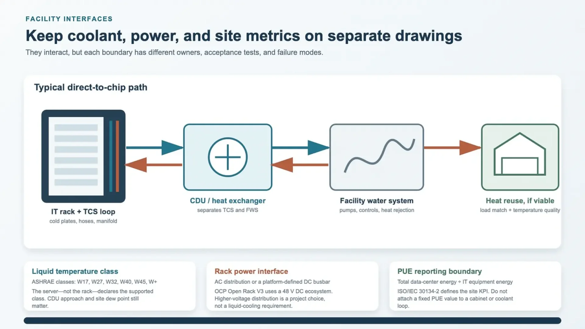
Liquid cooling touches the electrical and facility systems, but it does not make them one specification. Keeping the boundaries separate makes ownership and acceptance much clearer.
Name the rack ecosystem before the power hardware
IEC 60297 defines the 482.6 mm (19 in.) rack series; one rack unit is 44.45 mm (1.750 in.). OCP Open Rack uses a 21 in. equipment bay and a 48 mm OpenU, with Open Rack V3 built around a 48 V DC ecosystem. Adapters exist in some configurations, but the rail, power, and manifold interfaces are not interchangeable by default.
Liquid cooling does not require high‑voltage DC. The project may use AC distribution, a 48 V busbar, or another platform‑defined architecture. Put the released connector, busbar or PDU, fault‑current boundary, cable route, clearances, bonding, and service method on the rack drawing. Avoid broad efficiency claims unless they come from the complete, measured power path.
Let the server declare the liquid temperature class
ASHRAE's liquid‑cooling classes are W17, W27, W32, W40, W45, and W+, with the class name indicating the upper supply‑temperature limit. The server declares which class it supports. The rack still needs the technology cooling system (TCS) flow, pressure drop, coolant, connection type, and residual air condition. The CDU then separates the TCS from the facility water system (FWS), with an approach temperature that has to be included in the design.
Treat heat reuse as a matched‑load calculation
Warm return water can improve the quality of recoverable heat. ASHRAE describes installations using roughly 40–45°C (104–113°F) warm‑water cooling, but that does not turn every liquid‑cooled data center into a useful heat source. The receiving load must exist at the same time, at a usable temperature, and close enough that pumps, piping, heat exchangers, controls, and heat‑pump energy do not erase the value.
Start with an annual temperature and load profile, not a single return‑water number. Document minimum and maximum flow, approach temperature, seasonal demand, backup heat rejection, water chemistry, and who operates the receiving system.
Keep PUE at the site boundary
ISO/IEC 30134‑2:2026 defines PUE as total data‑center energy divided by IT equipment energy across the specified measurement boundary and period. Cooling architecture can improve or worsen that result, but a cabinet cannot promise a site PUE on its own. This distinction removes a lot of misleading comparisons between cold plates, immersion tanks, and air‑cooled racks.
|
Four interface documents that prevent late changes •Rack mechanical ICD: rails, payload map, manifold, QDs, hose sweep, PDU or busbar, cables, doors, bonding, service and shipping envelope. •TCS schedule: coolant, supply/return temperature, flow, pressure drop, MAWP, materials, water class, sensors and isolation. •FWS/CDU schedule: facility temperatures, approach, heat exchanger duty, redundancy, controls, commissioning and heat-rejection path. •Energy boundary: the meters, period, exclusions, and operating state used for PUE or heat-reuse reporting. |
6.Build the QC Plan Around the Actual Failure Modes
Rack geometry and coolant‑loop integrity are related, but they are not the same inspection. A square frame does not prove that a manifold is clean and leak‑tight. A passed pressure test does not prove that the rails align or that a server can be removed without bending a hose.
Make the mechanical checks measurable
The values below are reasonable starting targets for a custom full‑height rack, not universal requirements. The drawing should name the datum, support condition, measurement method, temperature, installed configuration, and pass/fail rule.
|
Check |
Example starting target |
Context to put in the test plan |
|
Frame squareness |
Diagonal difference ≤ 3 mm |
Reference faces, support points, doors and panels installed or removed |
|
Mounting-rail plane |
Coplanarity within 1 mm |
Top/middle/bottom points, rail torque, defined front and rear datums |
|
Manifold bracket datum |
±1.0 mm or connector stack-up |
Hand-mate versus blind-mate QD, float mechanism, functional mating gauge |
|
Load and function |
Released payload map; no binding |
Center of gravity, partial loads, supports, deflection and residual set under and after load |
|
Powder coat |
60–100 μm DFT if specified |
Coating system, sample locations, masked zones and measurement method |
Qualify the fluid hardware to its own boundary
A production leak check may use pressure decay, vacuum decay, tracer gas, or another agreed method. State the test medium, pressure, stabilization time, hold time, allowable decay or leak rate, temperature compensation, component configuration, and safety controls. Do not apply a generic pneumatic pressure to assembled servers, QDs, sensors, or hoses just because the rack frame can withstand it.
OCP's rack‑manifold qualification white paper gives useful examples: minimum burst pressure at 3 × maximum allowable working pressure and a 5,000‑cycle pressure‑upset test are included in its qualification discussion. Those are not generic factory settings. The released component ratings and customer specification still govern the actual program.
The same guidance calls for attention to sealing surfaces, including Ra ≤ 1.6 μm (63 μin.) in certain O‑ring applications, and for post‑weld cleaning and passivation where applicable. Record the wetted‑material revision, cleaning or flushing status, connection torque, caps, valve position, sensor continuity, and any preservation used for shipment.
Inspect what the rack factory actually owns
If the factory supplies only the frame, manifold brackets, and drip tray, its certificate should not imply that the final cooling loop was qualified. If it installs the manifold and QDs, the traveler should include those part revisions and the agreed fluid test. Clear scope is part of quality control.
A useful first‑article record combines dimensions, rail fit, load configuration, coating readings, bonding checks, controlled photos, and coolant‑hardware results. It also records what was not installed. That last detail saves time during commissioning.
7.Make the Choice From Project Constraints
The useful question is not whether liquid cooling is more advanced. It is whether a particular server, facility, maintenance team, and budget can support the complete operating model without creating an unserviceable enclosure.
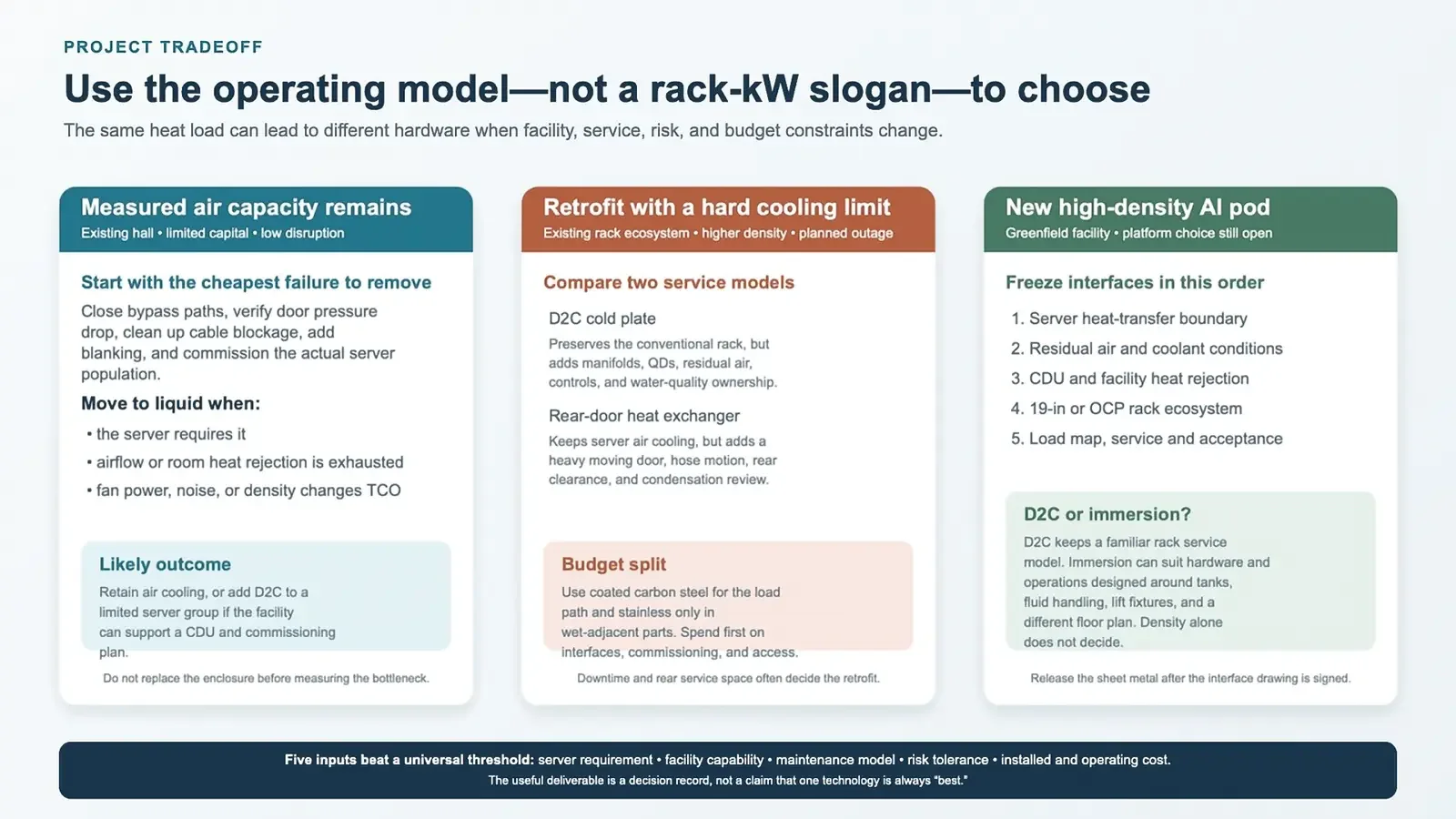
Scenario 1: a budget‑limited retrofit with measured air margin
If the existing hall can deliver the required airflow and reject the heat at the target load, keep the rack and fix the inexpensive problems first. Close bypass gaps, verify door pressure drop, remove cable blockage, use blanking panels, and commission the actual server population. Replacing sheet metal will not correct a facility airflow problem.
When only a small group of CPU or GPU servers is constrained, D2C may be a reasonable phased step if the site can support a CDU, controls, water quality, and an outage plan. The rack can stay mostly conventional, but the rear service zone and residual air path still need to be reworked.
Scenario 2: a retrofit with a hard room‑cooling limit
D2C and a rear‑door heat exchanger solve different problems. D2C removes heat at selected devices and adds manifolds and QDs. A rear‑door unit keeps the server air path but shifts heat to liquid at the cabinet. Downtime, rear clearance, door handling, piping route, condensate risk, and the maintenance team's familiarity often decide between them.
For the enclosure budget, a coated carbon‑steel load path with stainless wet‑adjacent parts usually puts material where it matters. Spend first on fit, access, leak detection, commissioning, and a clear test boundary. An all‑stainless rack can cost more without reducing the main project risk.
Scenario 3: a new high‑density AI pod
Freeze the server heat‑transfer boundary first: liquid capture, residual air, coolant, temperature class, flow, pressure drop, and failure response. Next, set the CDU and facility heat‑rejection path. Then choose the 19 in. or OCP rack ecosystem and release the load map, power, manifold, cable, service, shipping, and QC interfaces as one controlled package.
Immersion can fit a platform designed around tank service, fluid handling, lifting fixtures, and a different floor plan. D2C keeps a more familiar rack maintenance model. Density alone does not settle the choice; compare hardware compatibility, service time, fluid management, floor loading, safety review, supply chain, and lifecycle cost.
8.Use the Enclosure Specification as the Decision Record
A liquid‑cooled AI rack enclosure is ready for fabrication when the cooling boundary, rack ecosystem, payload map, service envelope, materials, power and coolant interfaces, and acceptance tests agree. That is a much more useful milestone than calling a cabinet “liquid ready.”
The final specification should say what heat stays in air, what moves to liquid, where every interface sits, who owns it, and how the assembled system will be verified. With those decisions recorded, the sheet‑metal tradeoffs become straightforward—and future server refreshes have a technical baseline instead of a collection of assumptions.
Key Takeaways
- Never start sheet‑metal design purely from high‑level labels such as “liquid‑cooled rack”. First define your heat‑transfer boundary (D2C cold‑plate, rear‑door exchanger or immersion tank).
- Residual air‑cooling loads often persist even with liquid‑cooled IT hardware; obtain official server‑vendor performance data before modifying cabinet airflow hardware.
- Manifold assemblies, drip‑tray geometry and service‑access clearance must account for real‑world technician reach, tool travel, and hose‑bend constraints, not only isolated component CAD fit.
- Immersion cooling creates tank‑style pressure, floor‑load, sealing and fluid‑compatibility requirements that depart significantly from conventional server‑rack design rules.
- Optimize material selection by separating primary load‑path structures from wet‑adjacent zones; full stainless construction is rarely required for complete indoor racks.
- Mechanical dimensional inspection and coolant‑loop leak testing represent independent QC workflows; passing one test cannot substitute for the other.
- Assign clear supplier ownership for every interface (mechanical, coolant, power, facility) to reduce late‑stage project surprises.
If you are finalizing drawings or RFQ requirements for custom liquid‑cooled AI rack enclosures, our engineering team can review your sheet‑metal specifications for common fabrication pitfalls. Contact us to discuss your project.